
User Manual


INSTALLATION & OPERATION MANUAL 14-0302 REV 4 (11/22)
PAGE
6
OF 16
The Market Forge Steam-it model ST-E Electrically Operated Pressure Cooker.
stainless steel. Door shall be self-sealing inside type which can’t be opened under pressure. Door is 12 gauge
stainless steel, removable for cleaning without tools.
Door gasket is a one piece mold, replaceable without tools or cement.
Cooking compartment has a capacity of (3) 12” x 20” x 2 1/2” or (2) 12” x 20” 4” pans. Removable pan supports are
end of cooking cycle. Unit includes 0-60 minute timer, a safety valve, steam pressure gauge, and will be completely
serviceable from the front.
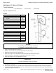
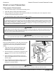
Set steam-it on counter, using 4” (102mm) legs provided with unit or an optional stainless steel stand with
under-shelf. If your steam-it includes a water-cooled exhaust condenser, we recommend the use of the steam-it
stand, part number 95-6060. First, level unit in place. Then adjust front legs to pitch the unit forward 1/4” (6mm)
to insure positive drainage of the cylinder.
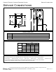
Connect to proper electrical supply box and disconnect switch as shown on one of the following schematic
diagrams 208 or 230 volts, single or three phase. Connection is located behind the terminal box cover at the lower
left side of unit. Whether the supply current is 208 volt or 240 volt, single or three phase, all control circuits are 120
volts. In order to accomplish this connection, a current-carrying grounded neutral must be provided. Thus, a three
phase system must be 4-wires and a single phase system must be 3-wires. If a current-carrying grounded neutral
is not available from the power source, a separate 120 volt circuit must be run. Most electrical codes require, and
we recommend, that a separate disconnect switch be located within sight of the sterilizer. When separate 120 volt
control circuit must be run, this must also be part of the disconnect box assembly.
Connect 1/2” (13mm) nominal tubing exhaust to outside vent connection located on the top of the control housing.
IMPORTANT
Exhaust line must be vented to the outside to eliminate the exhausted steam and the accompanying noise from
entering the room. Use 1/2” (13mm) copper tubing or suitable alternate. Length of the line should not exceed 15 feet
(4.5 meters) and should have a minimum of bends. The line should slope downward after leaving the sterilizer in order
to insure condensate drainage.
If outside venting is not possible, an optional water-cooled condenser is available for connection to an open drain. For
details of the installation on the ST-E, see page 5.
If a recording thermometer is provided, see installations with the thermometer for installation.