
Instruction Manual

INSTALLATION & OPERATION MANUAL 14-0268 REV 9 (07/22)
PAGE
5
OF 20
SIRIUS II -
NOTES
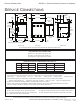
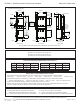
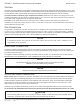
WATER SUPPLY AND DRAIN SPECIFICATIONS
A
Sirius II-8
Sirius II-10
Sirius II-12
B
C
24.00 [610]
19.00 [483]
3.88 [98]
Stacking
Collor
4.75 [121]
4.13 [105]
A
56.63 [1438]
63.63 [1616]
70.63 [1794]
B
C
A/B
15.38 [391]
22.38 [568]
C
A/B
26.25 [667]
33.25 [845]
C
6.00 [152]
2.00 [51] 20.00 [508]
32.50 [826]
28.75 [730]
17.75 [451]
Pull out service
drawer
Door in
open position
2.00 [51] 22.00 [559]
4.75 [121]
5
[127]
Flue
Steam Vents
Gas in
1/2” NPT
(each unit
required
gas line)
3.25 [83]
Water in (each unit
requires water line)
21.00
[533]
8.50 [216]
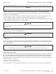
SPECIFICATIONS AND COMPARTMENT PAN CAPACITY
GAS PRESSURE AND CONNECTIONS
Pans Sirius II-8 Sirius II-10 Sirius II-12
12” x 20” x 2.5” 8 10 12
12” x 20” x 4” 4 6 8
12” x 20” x 6” 2 3 4
Sirius II-8 Sirius II-10 Sirius II-12
Voltage 120V 120V 120V
27,000* 27,000* 27,000*
Gas NPT 1/2” 1/2” 1/2”
Natural - 3.5” WC required, not to exceed 13.5”
Propane - 9” WC required, not to exceed 13.5”
Gas pipe size: 1/2” NPT required as a minimum
Good quality water feed is the responsibility of the owner. Water quality must be within the following general guidelines.
TDS: 40-125 ppm Hardness: 35-100 ppm pH: 7.0 - 8.5 Silica: <13 ppm Chlorides: <25 ppm Chlorine: <0.2 ppm Chloramine: <0.2 ppm
The best defense against poor water quality is a water treatment system designed to meet your water quality conditions.
Pressure: 25(min)-50(max) PSI Connections: Trough drain: 1/2 MNTP Drain out: 1” FNPT Water: 3/4” male garden hose
Appliance to be installed with backflow protection according to federal, state or local codes.
The drain piping must consist of temperature resistant material, greater than 160°F, and be of adequate diameter not to cause flow
restriction. Improper materials may deform and cause restrictions, thus affecting performance.
Each single compartment has a separate rear exiting drain
plumbed directly into the stacked steamers main drain/vent line.
4” clearance left mandatory, right and rear is recommended.
Location near a floor drain is recommended.
4” stacking collar between units (included when ordered)
The manufacturer reserves the right to modify materials and specifications without notice.
DIMENSIONS ARE IN INCHES [MM]
FRONT VIEW SIDE VIEW REAR VIEW