
Operating instructions


5
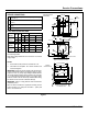
InstallatIon
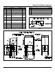
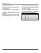
Item Part No. Description Qty
1 95-2119 Steam condensing unit 1
2 95-2219 Thermostat Box Assy. 1
3 95-0086 Exhaust line 1
5 15-7057 Copper tubing 3/8 OD 22.25”
6 10-1775
Rd. Hd. Mach. Screw,
1/4-20
2
7 10-2500 Lockwasher, 1/4 2
8 10-2308 Hex Nut, 1/4-20 2
9 10-1812
Rd. Hd. Mach. Screw, 10-
32
2
10 10-2505 Lockwasher, 10 2
11 10-2340 Hex Nut, 10-32 2
12 95-4009 Front Template (7” Lg)
1
13 95-4010 Back Template (11” Lg) 1
SERVICE CONNECTIONS REQUIRED
A 1/2” IPS Cold Water Connection
B 1” IPS Drain Connection (See Note 3)
C 115V Elec. Connection 7/8 Ø knockout (cond. unit)
D Electrical Connection
Figure 2
Optional Cold Water Condenser
Figure 3