
Operating instructions

4
InstallatIon
Installation Instructions
INSTALLATION
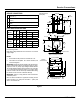
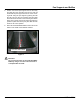
Set sterilizer on counter, using the 6” (152mm) legs pro-
vided or assemble the optional stainless steel stand with
under-shelf.
If your Sterilmatic includes a water-cooled exhaust con-
denser, we recommend the use of the Sterilmatic stand,
part number 95-6060.
First, level unit in place, then adjust rear legs to pitch the
unit forward 1/4” (6mm) to insure positive drainage of the
cylinder.
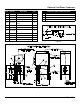
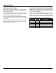
ELECTRICAL
Connect to proper electrical supply box and disconnect
switch as shown on one of the following schematic dia-
grams - 208 or 240 volts, single or three phase. Connec-
tion is made from the rear of the unit, through the conduit
to the terminal box located at the front of the unit.
Electric supply connection for STM-E & STM-EL
Connect to proper electrical supply as indicated on name-
plate on top of unit. The power supply cord is brought in
from the rear of the unit, through the conduit and the con-
nection is made at the terminal box located at the front of
the unit.
Electric supply connection for STM-EX & STM-ELX
(export models)
Connect to proper electrical supply as indicated on name-
plate on top of unit. Connection is made from the rear of
the unit, through the conduit to the terminal box located at
the front of the unit. All control circuits are 220 volts.
In order to accomplish this, a current-carrying grounded
neutral must be provided.
Thus, a three phase system must be 4-wires. Most elec-
trical codes require, and we recommend, that a separate
switch be located within sight of the sterilizer.
OUTSIDE VENTING
Connect 1/2” (13mm) nominal tubing exhaust to outside
vent connection located on top of unit, within the control
housing.
IMPORTANT: Exhaust line must be vented to the out-
side to eliminate the exhausted steam and the accom-
panying noise from entering the room.
Use 1/2” (13mm) copper tubing or suitable alternate. The
overall height and length of the line should not rise more
then 4 feet (1.2 meters) above the unit and exceed 15 feet
(4.5 meters) with a minimum of bends. The line should
slope downward after leaving the sterilizer in order to in-
sure condensate drainage.
WATER-COOLED EXHAUST CONDENSER
If outside venting is not possible, an optional water-cooled
condenser is available for connection to an open drain. If
required order part no. 95-0436 kit.
RECORDING THERMOMETER
If a recording thermometer is provided, refer to installation
guide provided with recorder.
TRAY SUPPORTS
Install side tray supports. Tray supports are attached by
means of key-hole clearance slots which are slipped over
studs located on the sides of the Sterilmatic chamber.
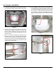
BAFFLE INSTALLATION
To insure maximum drying of packs, a bafe is supplied
with your Sterilmatic. Place perforated splash bafe in
bottom of the sterilizing chamber. Install small bafe with
no perforation at the rear of the upper tray support chan-
nel.
NOTE: The perforated bafe is not to be used as a shelf
to place media or other items. It is intended to
eliminate splashing.
OPERATION CHECK
To check for proper operation of unit:
3. Close drain valve by turning handle clockwise.
WARNING
DO NOT OPEN DRAIN VALVE WHILE UNIT
IS OPERATING. PREMATURE OPENING MAY
RESULT IN SCALDING OF OPERATOR.
4. Fill chamber with 4 to 6 quarts (3.7 to 5.6 liters) of
ordinary tap water. DO NOT USE DISTILLED OR DE-
IONIZED WATER.
5. Close chamber door.
6. Set exhaust selector to INSTRUMENTS AND PACKS
(fast exhaust) or LIQUIDS (slow exhaust).
7. Set timer to 15 minutes. Cycle will go to completion
automatically.
NOTE: Cycle timer will not start until sterilizing
temperature is obtained.