
Operating instructions

3
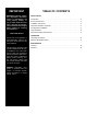
InstallatIon
Service Connections
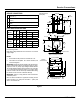
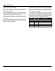
SERVICE CONNECTIONS
A Drain - 1/2” (13mm) N.P.T. of 5/8” (16mm) OD copper
(see note 1)
B Steam Exhaust Connection - 3/8” (10mm) IPS (see
note 2)
C Electrical Connection - (*see electrical specifications
table)
D Power Supply
ELECTRICAL SPECIFICATIONS
Domestic
Models
kW Hz
1 Phase
3 Phase
208V 240V 208V 240V
STM-E
STM-EL
9.3 60 45A - 26A -
12.4 60 - 52A - 30A
Export
Models
kW Hz
1 Phase
3 Phase
220V 240V 220/380V 240/415V
STM-EX
STM-ELX
10.4 50 48A - 16A -
12.4 50 - 52A - 18A
Unit must be grounded.
Main supply voltage fluctuations are not to exceel ± 10% nominal
supply voltage.
NOTES:
1. An air break must be provided if a unit drain line is run.
2. Vent exhaust to atmosphere. B1 is actual connection, but
must exit casing at B.
IMPORTANT: Exhaust line must be vented to the outside to elimi-
nate the exhaust steam and the accompanying noise from enter-
ing the room. Use 1/2” (13mm) copper tubing or suitable alternate.
The overall height and length of the line should not rise more then
4’ (1.2 meters) above the unit and exceed 15’ (4.5 meters) with a
minimum of bends. The line should slope downward after leaving
the sterilizer in order to ensure condensate drainage.
IMPORTANT: Failure to comply with this outline will affect the
sterilization process.
When an exhaust condenser is supplied; the following services
must be provided: 1/2” (13mm) IPS cold water: 1” (25mm) IPS
waste: 115V electrical line.
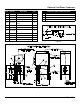
DIMENSIONS ARE IN
INCHES [MM]
D
CONDUIT
15.5
[394]
3.5 [89]
C
A
9.34 [237]
18.69 [475]
B
SEE
NOTE 2
4.75 [121]
B1
25
[635]
30
[762]
1.5 [38]
SEE NOTE 2
B
2 [57]
4.63 [117]
23
[584]
1 [25]
6 [152]
B1
A
4 [102] ADJ. LEGS
Customer provided Drain Catch Pan
Approx. 4-6 quarts (3.8-5.7 liters)
21 [533] CHAMBER
9 [230]
12 [305]
DOOR IN
OPEN POSITION
9 [228]
CLEARANCE
11 [280]
CLEARANCE
C
D
CONDUIT
3 [76]
Locate electric box as close to
sterilizer as possible and per
local electrical codes
Figure 1