
Operating instructions

9
InstallatIon
Optional Recording Thermometer
INSTALLATION FOR OPTIONAL RECORDING THER-
MOMETER
The optional Recording Thermometer may be surface or
panel mounted whichever is preferred.
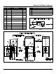
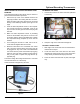
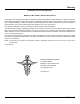
1. Remove the top cover of the sterilizer. Remove the
pipe plug located in the T-tting that also accommo-
dates the safety relief valve and which is connected
directly to the sterilizing chamber. (See gure to the
right)
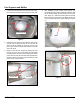
2. Insert the RTD temperature sensor of the tempera-
ture recorder through the rectangular cutout in the
top cover then into the pipe from which the plug was
removed.
3. Make sure RTD temperature sensor is protruding
down into the sterilizer cavity but not too much so as
to interfere with the sheet metal bafe plate. Tighten
the compression tting. Replace top cover onto the
sterilizer.
4. For mounting the recorder on a wall, refer to the re-
corder manual supplied with the recorder.
5. Electrical connections: The 115/120VAC unit comes
with a 6’ power cord and three prong plug. This can
be plugged into any 120V outlet. The 220/230VAC
unit comes with a 6’ power cord and three prong plug.
However, due to the many varieties of plugs and out-
lets you may need to replace the plug with the ap-
propriate plug.
The Future Design Recording Thermometer is a 24-hour
clock and should be run continuously.
Charts should be changed every 24 hours.
Figure 9
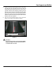
TO REMOVE THE CHART
1. Unscrew and remove the chart ‘hub’ knob (attached
to the chain).
Remove Plug
Figure 10
2. Grasp the edge of the chart and lift straight off.
TO INSTALL A NEW CHART
1. Slide edge of the chart under the two raised tabs lo-
cated under the stylus.
2. Locate the center hole of the chart over the center,
threaded rod. Rotate chart to line up the current time
of day directly underneath the stylus print head.
3. Screw the chart ‘hub’ knob back in place, hand tight
only.