OWNER’S MANUAL PREMIER SERIES HIGH PERFORMANCE ELECTRIC CONVECTION OVEN MODELS: m 3000 m 3092 WARNING: FOR YOUR SAFETY: Improper installation, adjustment, alteration, service or maintenance can cause property damage, injury or death. Read these installation, operation and maintenance instructions thoroughly before installing or servicing this equipment. Do not store or use gasoline or other flammable vapors or liquids in the vicinity of this or any other appliance.
TABLE OF CONTENTS INTRODUCTION ................................................................................................................ IMPORTANT ............................................................................................................ INSTALLATION, OPERATION & SERVICE PERSONNEL ...................................... SHIPPING DAMAGE CLAIM PROCEDURE ........................................................... ii ii ii ii GENERAL ....................................................
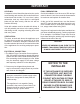
INTRODUCTION IMPORTANT: Service of the equipment should be performed by qualified personnel who are knowledgeable with Market Forge cooking equipment. Safe and satisfactory operation of your equipment depends on proper installation. Installation must conform with local codes, or in the absence of local codes, the Natonal Electrical Code, (ANSI NFPA-70 Latest Edition). Canadian Electrical Codes (C.S.A. C22.1).
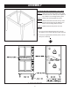
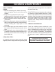
GENERAL IMPORTANT: To perform maintenance and repairs of the appliance, please contact the factory, factory representative, or the nearest local authorized service company. SINGLE OVEN: Assemble the leg/stand assembly as follows: 1. Remove legs from package. 2. Secure top frame parts to the legs with bolts provided (long angle - front and back. short angle - sides). RATING PLATE: The rating plate is located in front of the oven below the oven section.
ASSEMBLY STACKING INSTRUCTIONS MODEL 3092 OVENS STEP 1. Attach (4) foot mounting plates and (4) bullet feet onto bottom ove. Set top oven in place on top of bottom oven and slign them in place. STEP 2. Fasten rear mounting plates as shown. STEP 3. Remove the bottom front trim from top oven and the top front trim from the bottom oven. Fasten front mounting plates as shown. STEP 4. Reattach the front trim pieces to ovens. NOTES: 1. Top oven is shown with the bottom trim removed.
IMPORTANT LEVELING: A carpenter’s level should be placed on the oven’s center baking rack and the unit leveled both frontto-back and side-to-side. If it is not level, cakes, casseroles, and any other liquid or semi-liquid batter will not bake evenly, and the unit will not function efficiently. FINAL PREPARATION: On initial installation, turn the oven to 250o and operate for about 1 hour, then reset the thermostat to its maximum and operate for another hour.
CLEANING & MAINTENANCE DAILY CLEANING: OVENS: 1. Remove the baking racks. Wash in hot soapy water and replace after the rest of the oven is cleaned. 2. Scrape off any food particles with a nylon griddle scraper. Be very careful about scraping the porcelain finish on the oven liner panels. 3. Wash all the above with hot soapy water, then reassemble. 4. Baked on spills may be loosened and stubborn stains removed with ordinary houshold ammonia and scrubbing with a nylon pad in a cold oven only. 5.
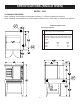
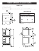
SPECIFICATIONS (SINGLE OVEN) MODEL: 3000 CLEARANCE REQUIRED: CLEARANCE REQUIRED: When installing ovens against combustable 6” (152mm) clearance is required. When installing ovens against combustable surfaces 6” surfaces 152mm clearance is required. When installing ovens against non-combustable surfaces (rear or side walls) 0” clearance is required. When installing ovens against non-combustable surfaces (rear or side walls) 0” clearance is required.
SPECIFICATIONS (STACKED OVEN) MODEL: 3092 CLEARANCE REQUIRED: When installing ovens against combustable surfaces 6” (152mm) clearance is required. When installing ovens against non-combustable surfaces (rear or side walls) 0” clearance is required. SERVICE CONNECTIONS Electrically Operated EC Electrical Connection - Connection for incoming power supply wire on terminal block. EP Power supply - 1 3/8 (44mm) access holes for power supply wires. Use wire suitable for at least 90°C.
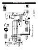
WIRING DIAGRAM 7
PARTS LIST 8
PARTS LIST ITEM # PART # DESCRIPTOPM QTY.
PARTS LIST 44 93-0076 DIVERTER - BOTTOM 1 45 93-0077 DIVERTER - SIDES 1 46 93-0078 DIVERTER - TOP 1 47 93-0074 LEG 6” S/S - WITH ADJUSTABLE FOOT (TSCV-2) 1 48 93-0075 LEG PLATE ASSY. (TSCV-2) 1 52 93-0048 RACK GUIDE - R/H 1 93-0050 RACK GUIDE - L/H 1 53 93-0049 RACK 1 54 93-0069 TOP PANEL 1 56 93-0047 LEG ASSY.
PARTS LIST Fig. 5 Heating Elements ITEM # PART # DESCRIPTION QTY. 1 98-4066 208 Volt Heating Elements (Nest of Three) 1 Set 2 98-4067 240 Volt Heating Elements (Nest of Three) 1 Set 3 98-4065 480 Volt Heating Elements (Nest of Three) 1 Set Fig. 6 Terminal Block Contactor & Wire Assembly 11 ITEM # PART # DESCRIPTION QTY. 1 97-4616 Terminal Block Assy. 1 2 10-5944 Contactor 40 Amp.
PARTS LIST Fig. 7 Electrical ITEM # PART # DESCRIPTION QTY.
PARTS LIST PREMIER SERIES 1 9 HEAT ON THERMOSTAT O FF 0 60 5 ITEM # PART # DESCRIPTION 1 93-0300 Market Forge Premier Lexan Decal 10 QTY. 93-0023 Thermostat 60” Capline 1 3 REF.