OWNER’S MANUAL CAPELLA STEAMER MODELS: INSTALLATION OPERATION MAINTENANCE STEAM COOKING CAPELLA - 4 CAPELLA - 6 CAPELLA - 8 CAPELLA - 10 CAPELLA - 12 GUIDELINES PARTS LISTS PARTS & SERVICE /DNHVLGH $YHQXH %XUOLQJWRQ 97 Tel: ( ) Fax: ( ) ZZZ PILL FRP 3 1 5HY $
TABLE OF CONTENTS IMPORTANT NOTES FOR SAFETY, INSTALLATION AND OPERATION ............................................... 4 A. INTRODUCTION ............................................................................................................................ 5 1) Product Description .......................................................................................................... 5 2) Safety Features ...............................................................................................
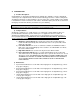
IMPORTANT NOTES FOR SAFETY, INSTALLATION AND OPERATION ! WARNING: This is the safety alert symbol. It is used to alert you to potential personal injury hazards. Obey all safety messages that follow this symbol to avoid possible injury or death. ! WARNING: Improper installation adjustment, alteration, service or maintenance can cause property damage, injury or death. Read the installation, operating and maintenance instructions thoroughly before installing or servicing this equipment.
A INTRODUCTION 1) Product Description: Congratulations on purchasing the Market Forge Capella. The Capella is a single compartment countertop or two-compartment floor model steamer featuring pressureless steam cooking and a circulating fan inside the cooking chamber to speed cooking. The cooking chamber of the Capella is treated with a scratch resistant, non-stick surface. A low water probe prevents the steamer from running dry an a ball valve drain is provided for easy safe draining.
4) Service Contacts: Should repairs be required, a network of authorized agencies is available to assist with prompt service. A current Directory of Authorized Service Agencies may be obtained by contacting: Market Forge Industries, Inc. Web Site: www.mfii.
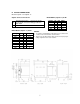
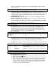
B SERVICE CONNECTIONS Models: Capella – 4 & Capella – 6 Capella Service Connections: EC D ELECTRICAL (Capella - 4) 60 Hz Electrical Connection – 1 1/8” knock-out hole for electrical connection. Rating provided on data label. Drain – A 6 ft. removable drain hose Voltage 208 240 208 240 480 pH 1 1 3 3 3 kW 8 8 8 8 7.2 Amps 39 33 22 19 9 ELECTRICAL (Capella - 6) 60 Hz NOTES: Voltage 208 240 208 240 208 240 208 240 480 pH 1 1 3 3 1 1 3 3 3 kW 8 8 8 8 9.8 9.8 9.8 9.8 9 Amps 38.5 33.3 22.2 19.
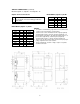
SERVICE CONNECTIONS (continued) Models: Capella – 8, Capella – 10 & Capella – 12 Capella Service Connections: EC D ELECTRICAL (Capella - 4) 60 Hz Electrical Connection – 1 1/8” knock-out hole for electrical connection. Rating provided on data label. Drain – A 6 ft. removable drain hose Voltage 208 240 208 240 480 pH 1 1 3 3 3 kW 8 8 8 8 7.2 Amps 39 33 22 19 9 ELECTRICAL (Capella - 6) 60 Hz NOTES: Voltage 208 240 208 240 208 240 208 240 480 pH 1 1 3 3 1 1 3 3 3 kW 8 8 8 8 9.8 9.8 9.8 9.
C INSTALLATION 1) Damage Inspection: Reporting shipping damage is the responsibility of the purchaser. Do not discard packaging if filing a freight damage claim. Upon receipt of steamer immediately inspect the exterior of packaging for damage. Remove wrapping. Inspect the exterior of the Capella for visible shipping damage. 2) Unpacking / removal from pallet: To remove the steamer from the pallet, carefully cut the strapping.
hole, fits over the pre-installed rack screws at the top of the cooking chamber wall. The curved wires on the rack should be facing to the front of the steamer. Repeat this process for the rack mounted on the other side. These racks are designed to be removed easily for cleaning. 13) Function tests / inspection: Once your steamer is in place and properly leveled, plumbed and wired, test unit to make sure it is functioning properly.
water level sensing probe still needs to be cleaned, both lights will remain on until the probe is cleaned. CAUTION: Do not add water to a hot, dry cooking chamber. Damage to the cooking chamber may result. If the cooking chamber has run dry, let it cool before refilling. 4) Clean probe light: If the CLEAN PROBE light (red) is illuminated, the water level sensing probe is unable to sense water. The probe is on the lower left side of the cooking chamber.
! WARNING: The reservoir water may still be hot. It is advisable to let the water cool down prior to draining. NOTE: Opening the steamer door will speed the cooling process. It is also advisable to leave the steamer door open when not in use. This will lengthen the life of the door gasket. F CLEANING GUIDELINES 1) Daily Cleaning Once the power is off and the reservoir has been drained, a simple cleaning process should be followed: WARNING: The cooking chamber is designed to retain heat.
Make sure the steamer is off and cool. Drain water from the cooking cavity and wipe away any food debris. Make sure the drain valve is closed. Pour one pound of descaling powder per steamer into the bottom of the cooking cavity. NOTE: One pound is equal to 16 scoops (measuring scoop included), or one-half of a 2lb. jar of descaling powder. For Capella (manual water fill) Steamer: Pour 2 ½ gallons water into the bottom of the cooking chamber and set the control to Steam (#2) position.
G STEAM COOKING GUIDELINES 1) Cooking with atmospheric / pressureless steam: Atmospheric or pressureless steaming is perfect for a la carte cooking. The door can always be opened during cooking to add or remove pans of food, to season food or to check on its progress. Multiple products can be cooked at one time because there is no crossover of cooking flavors in atmospheric steam. Large and small portions of food can be cooked at the same time.
c) Use solid pans where appropriate: scrambled eggs, rice, beans, dehydrated foods, prepared casseroles, sauces, cake or other desserts (you can bake a cake in atmospheric steam), and when you want to prevent food from dripping on a lower pan. d) When cooking proteins (meat, poultry or seafood) use a solid catch pan under the perforated pan. Accumulated juices can be used for soup stock, gravy or broth. e) Protein foods (meat, poultry or seafood) can be cooked in perforated or solid pans.
d) The cooking chamber is designed to retain heat. It may still be hot to the touch when cleaning. Wear protective gloves, or wait for the surface to cool before cleaning. Do not add cold water to a hot empty cooking chamber until unit has cooled down or damage may result. 2) Cautions a) Do not use utensils, steel wool, or other harsh abrasives to clean your steamer. Scratching of the non-stick surface and stainless steel casing may occur.
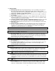
I WIRING DIAGRAM 1) 208/240 Volts Figure 1 17
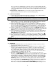
2) 480 Volts Figure 2 18
J ILLUSTRATED PARTS LIST 1) Cabinet Assembly 9 10 8 7 6a 1 2 6b 3 4 5 Figure 3 Full Front View Figure 4 Control Panel ITEM No. 1 1 2 2 3 3 4 5 6a 6b 7 8 9 10 PART No.
Cabinet Assembly continued 11 16 17 15 18 12 Figure 5 Oven Cavity (with Wire Racks) 14 13 19 Figure 6 Oven Cavity (no Wire Racks) ITEM No. 11 12 13 14 15 16 17 18 19 PART No.
2) Door Assembly 4 2 3 1 Figure 7 Inside View of Door ITEM No. 1 1 2 2 3 3 4 PART No.
3) General Assembly 1 2 3 4 5 Figure 9 Oven Rear View ITEM No. 1 2 3 4 5 5 PART No. 08-5433 10-2793 92-0225 92-0021 92-0008 92-0357 DESCRIPTION Copper Tubing, ½” Dia.
General Assembly (continued) 10 12 13 6 14 7 8 9 8 Figure 10 Inside Drain Line ITEM No. 6 7 8 9 10 11 12 13 14 PART No.
4) Control Panel Components & Heating Elements 2 Figure 12 View looking up from behind Control Panel 1 See Figure 14 For Details See Figure 15 For Details Figure 13 Left Side, Full view, Open ITEM No. 1 2 PART No.
Control Panel Components & Heating Elements (continued) 6 5 7 4 8 3 9 10 11 Figure 14 Slide Out Component Panel (Upper) ITEM No. 3 4 5 6 7 8 9 10 11 PART No.
Control Panel Components & Heating Elements (continued) 12 13 14 Figure 15 Stationary Component Panel (Lower) and Heating Elements 15 16 Figure 16 Upper Inside of Cavity View (with no Fan Baffle (Shield)) ITEM No. 12 13 PART No.
Control Panel Components & Heating Elements (continued) 17 18 19 20 21 Figure 17 Slide Out Control Panel ITEM No. 17 18 19 20 21 PART No.
5) Convection Fan and Motor Components 3 2 4 5 6 7 1 Figure 18 Fan Motor and Pulley Assembly 8 Figure 19 Convection Fan ITEM No. 1 2 3 4 5 6 7 8 PART No. 08-6905 08-5601 08-5600 92-0606 92-0605 92-0676 08-1414 92-0016 DESCRIPTION Fan Motor (230V) Pulley, .25” Dia. Bore, (22 Teeth) Pulley, .25” Dia.