4200 & 4292 HALF SIZE ELECTRIC CONVECTION OVEN PARTS AND SERVICE MANUAL EFFECTIVE SEPTEMBER 23, 2014 Superseding All Previous Parts Lists. The Company reserves the right to make substitution in the event that items specified are not available. ERRORS: Descriptive and/or typographic errors are subject to correction. MARKET FORGE INDUSTRIES 44 Lakeside Avenue, Burlington, Vermont 05401 USA Telephone: (802) 658-6600 Fax: (802) 860-3732 www.mfii.
TABLE OF CONTENTS REVERSING THE DOOR SWING. . . . . . . . . . . . . . . . . . . . . . . . . . . . . . . . . . . . . . . . . . . . . . . . . . . . . . . . 3 REMOVAL & REPLACEMENT OF PARTS.. . . . . . . . . . . . . . . . . . . . . . . . . . . . . . . . . . . . . . . . . . . . . . . . 4 THERMOSTAT CALIBRATION. . . . . . . . . . . . . . . . . . . . . . . . . . . . . . . . . . . . . . . . . . . . . . . . . . . . . . . . . . . 7 TROUBLESHOOTING.. . . . . . . . . . . . . . . . . . . . . . . . . . . . . . . . . . .
REVERSING THE DOOR SWING 1. Remove door handle, P/N 08-5205, by removing three slotted screws located on edge of handle. 7. Re-locate and install catch plate assembly at new location. 2. Loosen two upper hinge pin screws. Pin will drop into door. 8. Hold door in new position and allow hinge pin to slide out. Tighten two screws to hold pin in this position. 3. Remove door by tilting top of door outward while lifting door off of lower hinge pin. 9.
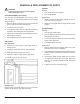
REMOVAL & REPLACEMENT OF PARTS GASKET WARNING Removal Disconnect oven from main power supply before working on oven. 1. Remove all screws from gaskets. 2. Remove all gaskets. DOOR ADJUSTMENT (OLD STYLE) Replacement The door was properly adjusted at the factory, if door does not open or close properly adjust the ball plunger catch as .follows: 1. Replace top and bottom metal gaskets on front off oven liner and screw in place. 1.
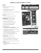
REMOVAL & REPLACEMENT OF PARTS MOTOR THERMOSTAT Removal Removal 1. Make sure main power supply is disconnected from oven. 1. Make sure power supply to oven is off. 2. Open control compartment cover. 2. Remove baffle and blower wheel. 3. Remove right side panel. 3. Remove racks and rack supports from oven compartment. 4. Open control compartment cover. 4. Remove baffle. 5. Remove motor bolt access plate. 5. Disconnect thermocouple lead wires from circuit board. 6.
REMOVAL & REPLACEMENT OF PARTS HIGH LIMIT Removal 1. Make sure power supply to oven is off. 2. Open oven door. ITEM PART NO. DESCRIPTION 1 08-6308 Reed switch (fan interlock) 2 99-6168 Reed switch mounting bracket 3 REF. Marr connectors, two 3. Remove all shelves and rack supports. 4. Remove baffle from right sire. 5. Unscrew fasteners from Hi-Limit on liner wall and pull out. 6. Remove wire leads from Hi-Limit. Replacement 1. Follow Hi-Limit Removal in reverse order.
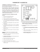
THERMOSTAT CALIBRATION THERMOSTAT CALIBRATION (OLD STYLE): The thermostat is a device which automatically limits heat input at or below the dial setting. Before attempting to calibrate thermostat, make sure that the thermostat is the cause of problems experienced. Check for improper electrical service, incorrect mixes over and under proofing, incorrect temperatures, and warping pans. Thermostats are calibrated and sealed by the original manufacturer before leaving their plant.
THERMOSTAT CALIBRATION CONTROL BOARD NOTE: New style board CANNOT BE CALIBRATED. Check thermocouple for fault in temperature control. If thermocouple is good, replace temperature control board.
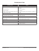
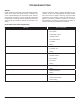
TROUBLESHOOTING PROBABLE CAUSE REMEDY Convector fan fails to operate. 1. Power to oven is off. 1. Locate external circuit breakers for power and place in ON position. 2. ON-OFF switch off. 2. Place in ON position. 3. Oven door open. 3. Close door. 4. Faulty cool down switch ON-OFF switch, door 4. Test each component and connecting wire, replace as reswitch, fan motor, wiring. quired. Oven will not heat with thermostat at maximum setting, fan operating. 1. Faulty thermostat wiring. 1.
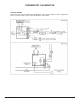
TROUBLESHOOTING WIRING All the electrical components of the model 4200 (ON-OFF switch, door switch, thermostat control, contactors, fan motor, and indicator light) are connected to each other by wiring shown on page 5. If all the electrical components are operating correctly and the incoming power has been checked, but the unit fails to operate, the fault lies in the wiring. Using an ohmmeter, wiring continuity between the connections, shown in the wiring diagram is readily verified.
WIRING DIAGRAM SEPTEMBER 23, 2014 11 4200 & 4292 HALF SIZE ELECTRIC OVENS
4200 OVEN SEPTEMBER 23, 2014 12 4200 & 4292 HALF SIZE ELECTRIC OVENS
4200 OVEN ITEM PART NO.
CONTROL PANEL ITEM PART NO. DESCRIPTION 1 10-6293 2 REF.
RIGHT SIDE VIEW ITEM PART NO. 1 09-7230 BLOWER MOTOR, 208/230V, 1/4 HP, 2 SPEED 2 08-6355 TEMPERATURE CONTROLLER, 208-240V 3 10-6649 TERMINAL BLOCK 4 10-6874 S.P.S.T.
DOOR ASSEMBLY ITEM PART NO.
OVEN COMPARTMENT INTERIOR Sorry - no drawing available PART NO.