OWNER’S MANUAL ELECTRIC COMPACT CONVECTION OVEN MODELS: 4200 4292 FORM NO.: S-2374 REV: A PRINTED IN U. S. A. 02/07 An Employee Owned Company 35 Garvey Street • Everett • MA • 02149 Tel: (617) 387-47100 • Fax: 1-800-227-2659 (Ex. MA) • (617) 387-4456 (MA and Overseas) E-mail: CUSTSERV@mfii.com • Website: www.mfii.
TABLE OF CONTENTS INTRODUCTION DESCRIPTION.................................................................................................................................1 OVEN COMPONENTS ....................................................................................................................1 BASIC FUNCTIONING ....................................................................................................................1 SERVICE .............................................................
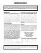
INTRODUCTION This service and parts manual contains general information, installation, operation, principles of operation, trouble-shooting and maintenance information for the Market Forge Model 4200 Electric Compact Convection Oven. Also included are parts lists, in which each replaceable part is identified and shown in an accompanying illustration.
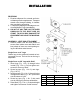
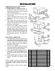
INSTALLATION RECEIVING 1. Examine shipment for external and internal damage and completeness. Transport crated oven through building, to installation area before unpacking. 2. 2. Report any damage or shortages to carrier and Market Forge immediately. 3. DO NOT AT ANY TIME LAY THE OVEN DOWN ON ITS TOP, RIGHT SIDE, OR FRONT. TO DO SO MAY DAMAGE THE EQUIPMENT AND VOID THE WARRANTY. ASSEMBLY - Vent Box Attachment 1.
INSTALLATION Stacked Ovens on 18” Legs with Shelf Stacking Instructions: 1. Fasten Item No. 1, stacking channel, to the bottom left side of top oven. Note - left channel has (2) holes. Use nut & washer (Item 3 & 4) front & rear. 2. Remove access panel from the right side of both ovens. 3. Remove knockouts from the top of the bottom oven and from the bottom of the top oven. 4. Place upper oven on top of lower oven with the right side stacking channel placed between.
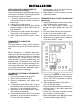
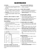
INSTALLATION OVEN CHECKOUT & ADJUSTMENTS: Door Adjustment (Old Style): The door was properly adjusted at the factory, if door does not open or close properly adjust the ball plunger catch as .follows: 1. 1. Remove adjusting wrench from back of manual and insert in notches on sides of ball plunger. 2. Loosen jam nut with wrench. 3. Turn adjusting wrench left or right until ball plunger engages in door striker plate for best operation. 4.
INSTALLATION 5
OPERATION PRINCIPLES OF OPERATION: Uniform distribution of heat within the oven is assured by continuous operation of a convector blower. Moving air continuously strips away a thin layer of moisture and cold air from the top of the food allowing more rapid heat penetration. Lower temperatures and shorter times than those used in conventional deck ovens ‘Can be used. In general, temperature settings can be reduced by 50°F (28°C) from recipe temperatures for conventional ovens.
MAINTENANCE CLEANING: 1. Clean interior of oven with a commercially available oven cleaner suitable for use on porcelain. 2. Racks, rack supports, and blower wheel may be cleaned by soaking in ammonia and water solution after removing them from oven. 3. Stainless steel parts maybe cleaned using a commercially available stainless steel cleaner. OVEN LINER GASKET REMOVAL: 1. Remove all screws from gaskets. 2. Remove all gaskets. GASKET REPLACEMENT: 1.
MAINTENANCE MOTOR REPLACEMENT: 1. Revere procedure above. 2. Check motor wiring to make sure blower turns clockwise when seen from front of oven. SWITCH REMOVAL: 1. Make sure power supply to oven is off. 2. Open control compartment cover. 3. Disconnect wire to switch. 4. Depress spring clips on switch and push forward. SWITCH REPLACEMENT: 1. Push switch into proper control panel opening until spring clips catch. 2. Reconnect wire to switch. 3. Close control cover. CONTACTOR REMOVAL: 1.
MAINTENANCE NEW STYLE INTERLOCK SWITCH REMOVAL: 1. Make sure power supply to oven is off. 2. Remove lower bottom trim, remove screws on end. 3. Remove screws from switch, to remove switch. 4. Remove marr connectors from leads, then remove switch. REPLACEMENT OF SWITCH: Follow New Style Interlock Switch Removal in reverse order. HI-LIMIT REMOVAL: 1. Make sure power supply to oven is off. 2. Open oven door. 3. Remove all shelves and rack supports. 4. Remove baffle from right sire. 5.
TROUBLE-SHOOTING GENERAL: The information in this section is intended to assist both the operator and service personnel in locating the general source of problems which may occur with the model 4200 compact convection oven. Before following any of the procedures gives in this section, the op- TROUBLE-SHOOTING GUIDE: PROBABLE CAUSE 1. Convector fan fails to operate. a. Power to oven is off. b. ON-OFF switch off. c. Oven door open. d. Faulty cool down switch ON-OFF switch, door switch, fan motor, wiring.
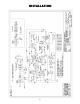
TROUBLE-SHOOTING WIRING: All the electrical components of the model 4200 (ON-OFF switch, door switch, thermostat control, contactors, fan motor, and indicator light) are connected to each other by wiring shown on page 5. If all the electrical components are operating correctly and the incoming power has been checked, but the unit fails to operate, the fault lies in the wiring. Using an ohmmeter, wiring continuity between the connections, shown in the wiring diagram is readily verified.
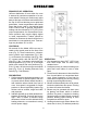
TROUBLE-SHOOTING ELECTRICAL CONNECTIONS CONTROL BOARD: Fig. 8 NOTE: New style board CANNOT BE CALIBRATED. Check thermocouple for fault in temperature control. If thermocouple is good, replace temperature control board.
ILLUSTRATED PARTS LIST GENERAL: This section contains a complete listing of all replaceable parts for the 4200 compact convection oven. For the purpose of parts identification, the unit is broken down into functional assemblies, and each assembly is shown in a pictorial view which is keyed to the accompanying part list. Each parts list contains the figure item number, the Market Forge part number and an abbreviated description.
ILLUSTRATED PARTS LIST Fig. 9 4200 Compact Convection Oven ITEM NO. PART NO.
ILLUSTRATED PARTS LIST Fig. 10 Fig. 10 Control Panel, Open ITEM NO. PART NO. DESCRIPTION 1 2 3 4 5 10-6293 REF.
ILLUSTRATED PARTS LIST Fig. 11 Fig. 11 Right Side View ITEM NO. PART NO. DESCRIPTION 1 2 3 4 5 09-7230 REF. REF. 10-6874 REF. BLOWER MOTOR, 208/230V, 1/4 HP, 2 SPEED TEMPERATURE CONTROLLER, 208-240V TERMINAL BLOCK S.P.S.T. RELAY, FOR REED SWITCH, 240V CONTACTOR, 208V, 40 AMP, 50/60 HZ 6 6A 7 8 8A 99-6108 99-6109 99-6140 09-6516 09-6599 HEATING ELEMENT COVER PLATE HEATING ELEMENT COVER GASKET ASSEMBLY, BLOWER MOTOR AND BRACKET SIREN AUDIO ALERT, 120V 6.
ILLUSTRATED PARTS LIST Fig. 12 Fig. 12 Door Assembly ITEM NO. PART NO. DESCRIPTION 1 2 3 4 5 08-5205 REF.
ILLUSTRATED PARTS LIST INSIDE OVEN COMPARTMENT PART NO. DESCRIPTION 99-5027 99-5057 99-5056 99-5052 99-5058 BAFFLE RACK SUPPORTS RACKS EXTERIOR TOP PANEL EXTERIOR REAR PANEL 99-5020 99-5035 10-0633 99-6176 99-6177 RIGHT SIDE ACCESS PANEL LEFT SIDE PANEL 4” ADJUSTABLE LEGS 28” HIGH STAND 18” STACKED KIT WITH STAND 4200/4292 REVERSING SWING OF DOOR (S): 1. Remove door handle, P/N 08-5205, by removing three slotted screws located on edge of handle. 2. Loosen two upper hinge pin screws.