3500 OWNER’S MANUAL WARNING: Improper installation, adjustment, alteration, service or maintenance can cause property damage, injury or death. Read the installation, operation and maintenance instructions thoroughly before installing or servicing this equipment. FOR YOUR SAFETY: Do not store or use gasoline or other flammable vapors and liquids in the vicinity of this or any other appliance. Post in a prominent location, instructions to be followed in the event the user smells gas.
TABLE OF CONTENTS INTRODUCTION BASIC FUNCTIONING . .......................................1 SERVICE . ............................................................1 CIRCUITS ............................................................11 INDICATOR LIGHTS ............................................11 BUZZER ...............................................................11 DOOR INTERLOCK SWITCH ..............................11 THERMOSTATIC SWITCH ..................................11 INSTALLATION ASSEMBLY ...
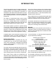
INTRODUCTION This service and parts manual contains general information, installation operation, principles of operation, trouble-shooting, and maintenance information for the Market Forge 3500 Pressureless Steam Cookers. Also included is a parts list in which each replaceable part is identified and shown in an accompanying exploded view. At the end of the set interval, timer contacts switch to shut off the cooking operation and sound a signal buzzer.
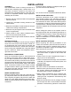
INSTALLATION ASSEMBLY: The Pressureless Cooker is factory-mounted on a cabinet base containing either a steam boiler or direct steam connection controls for the cooker. The assembled unit is shipped bolted to a skid, with cabinet feet in a separate container. Steps required for assembly are as follows: Equipment failure caused by inadequate water quality is not covered under warranty. CAUTION: PVC or CPVC are not acceptable materials for drains.
ing from the drain line. INSTALLATION shut off the power to the unit at its source then remove the control panel by unscrewing the eight mounting screws and pulling the panel away from the front frame. 4. Observe cooker operation for several minutes. Operation is correct if timer dials begin to rotate after a short delay period required for preheating. After the delay period plus the “4 minute” initial setting, the timer dials will return to the “0 minute” position, at which a buzzer sounds.
OPERATION STEAM SOURCE OPERATION: The Pressureless Cooker is supplied mounted on a cabinet containing either a steam boiler or controls for direct-connected steam. Manual controls are accessed by opening the cabinet door. The start-up procedure for the steam source is completed once before each daily operating period of the cooker. (For steam boilers, see instruction plate.) out of the compartment and then fully open the door. 7.
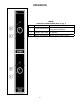
OPERATION ITEM 1 2 3 TABLE 1 CONTROLS & INDICATORS (Refer to Fig. 1) DESCRIPTION FUNCTION Controls cooking up to 60 minutes for Timer/Constant Steam uses constant operation. Indicated when lit that the cooker is Indicator Light (Red) in operation. Buzzer (Not Shown) Signals end of cooking period. Fig.
OPERATION TEST KITCHEN BULLETIN MODEL 3500 PRESSURELESS COOKER FACTS ON PARADE 1. Frozen vegetables should always be cooked in perforated 12” x 20” x 2 1/2” pans 7 1/2 lbs (34 kg) maximum per pan. 2. Frozen entrees should be underlined with a perforated pan for best results. If they are defrosted first, the heating time will be decreased. 3. Fresh foods may also be cooked in this unit.
OPERATION PRESSURELESS STEAM COOKING TIMER SETTINGS The 3500 Pressureless Cooker is a two compartment unit. Each compartment holds five 12” x 20” x 2 1/2” or three 12” x 20” x 4” pans. This unit enables the cook to prepare foods close to the time of service. The cooking times given are timer settings and should be set on a preheated compartment. There is a thermostatic time delay in each compartment that adjusts the total time depending on the temperature and amount of the food.
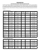
OPERATION VEGETABLES ITEM APPROX. RECOMMENDED FROZEN PAN SIZE, 12” x 20” WT. PER PAN PERFORATED Beans, Snap Green or Waxed NUMBER OF PANS TIMER SETTINGS IN MINUTES APPROX/ NO. COOKED SERVINGS PER PAN 6 lbs. (2.7 kg) 2 1/2” (65mm) 1-3 18-22 25-30 3 oz. (85 g) 7 1/2 lbs. (3.4 kg) 2 1/2” (65mm) 1-3 40-50 30-35 3 oz. (85 g) 6 lbs. (2.7 kg) 2 1/2” (65mm) 1-3 14-18 25-30 3 oz. (85 g) 9 lbs. (4 kg) 2 1/2” (65mm) 1-3 18-21 35-40 3 oz. (85 g) 6 lbs. (2.
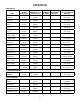
OPERATION MEAT, POULTRY, FISH ITEM APPROX. RECOMMENDED FROZEN PAN SIZE, 12” x 20” WT. PER PAN PERFORATED NUMBER OF PANS TIMER SETTINGS IN MINUTES APPROX/ NO. COOKED SERVINGS PER PAN Chicken, Cut-up 8 lbs (3.6 kg) 2 1/2” (65mm) 1-3 20-30 15-20 2 oz. Protein (55 g) Chicken, 4 lbs. Whole 3 each 4” (100 mm) 1-3 45-50 25-30 2 oz. Protein (55 g) Fowl, 5 lbs. or more, Whole 2 each 4” (100 mm) 1-3 50-60 20-25 2 oz. Protein (55 g) Fish, Fillets 3 lbs (1.
PRINCIPLES OF OPERATION is directed into the boiler (or direct-connected steam control) drain system. Steam inlet lines for compartments are equipped with normally closed solenoid valves operated by the electrical control circuits. The inlet valves are opened whenever the compartment control circuit is activated by use of the 60 minute timers.
PRINCIPLES OF OPERATION Fig. 2 Pictorial Diagram, Steam and Water Circuits INDICATOR LIGHTS: An indicator light is included for both compartments. The light remains on (red) at all times when the coinciding timer dial is set and the door interlock switch is closed. The light turns off at the end of the timed cooking duration. by the proximity of a magnet within the door. When the door is open, the switch contacts remain in the open position.
TROUBLE-SHOOTING GENERAL: The information in this section is intended to assist both the operator and service personnel in locating the general source of problems that may occur with the cooker. Before following any of the procedures given in this section, the operator should be thoroughly familiar with the operating instructions and the function of all controls that are described in the operating section of this manual.
TROUBLE-SHOOTING The electrical trouble-shooting procedures that follow require access to components and terminals of the electrical control panel shown in Fig. 6 on page 21. Electrical controls are reached by removing screws that fasten the control panel to the frame. The panel may be pulled forward for testing while interconnected to the cooker circuits or disconnected at the pin connection for complete removal and repair.
TROUBLE-SHOOTING Fig.
TROUBLE-SHOOTING 3. Connect an ohmmeter between terminals 1 and 3. 4. Rotate timer dial beyond the “0 Minute” point (any setting) to obtain a reading of zero ohms on the ohmmeter. If zero ohm reading cannot be obtained, timer contacts are defective and the timer must be replaced. 5. Move ohmmeter leads to terminals 1 and 4. 6. Rotate timer dial to “0 Minute” position (an audible click indicates correct position). If zero ohm reading cannot be obtained, the timer is defective and must be replaced. 7.
TROUBLE-SHOOTING is not obtained, the switch is defective. 4. Shut off cooker, disconnect ohmmeter leads, and replace wires on switch terminals. BUZZER: If the buzzer does not sound at the termination of the operator-selected timer setting (timer dial returned to “0 Minute” position), the fault may be a defective buzzer. Buzzer operation is verified using an AC voltmeter at buzzer coil connections with input power on and selector switch and coinciding timer dial set at the “0 Minute” position.
MAINTENANCE CAUTION: Under no circumstances should hardware (or parts) be replaced with a different length, size, or type other than as specified in the parts list. The hardware used in the cooker has been selected or designed specifically for its application, and the use of other hardware may damage the equipment and will void any warranty. exploded views of the 3500 Cooker. In most cases, disassembly procedures will be obvious from the exploded views.
ILLUSTRATED PARTS LIST Fig.
ILLUSTRATED PARTS LIST Fig. 4 Cabinet Assembly ITEM 1 2 3 4 5 6 7 8 9 10 11 12 13 14 15 16 17 18 19 20 21 22 23 24 25 26 27 28 29 30 31 32 33 34 35 36 PART NO. 98-3501 REF. 10-5859 08-4892 10-8823 98-3510 91-6838 10-9174 91-6477 08-4978 08-4866 08-4833 08-1207 91-7638 91-7639 98-3503 91-7619 98-3505 91-7690 08-6308 10-8105 10-3739 10-4586 10-9175 98-3511 91-7697 91-5700 91-6493 91-7684 08-4600 91-6475 91-6476 91-6492 91-6491 08-6538 91-6940 DESCRIPTION POST, REAR CONDENSER ASSY. (see Fig.
ILLUSTRATED PARTS LIST Fig. 5 Door Assembly ITEM 1 2 3 4 5 6 7 8 9 PART NO. 91-5729 91-5766 91-5731 91-5286 91-5745 09-1608 08-5027 91-5901 08-4600 DESCRIPTION OUTER DOOR INNER DOOR GASKET RETAINING PLATE DOOR GASKET DOOR HANDLE STRIKER MAGNET MAGNET BRACKET COMPRESSION SPRING 20 QTY.
ILLUSTRATED PARTS LIST Fig. 6 Control Panel Assembly ITEM 1 2 3 4 5 6 7 8 PART NO. 98-3504 98-3507 08-6464 08-6541 91-6471 10-7395 08-3826 10-5052 DESCRIPTION CONTROL PANEL ARTWORK, CONTROL PANEL 60 MIN. TIMER TERMINAL STRIP BRACKET, TERMINAL STRIP BUZZER KNOB, TIMER LIGHT, RED, ON/OFF 21 QTY.
ILLUSTRATED PARTS LIST Fig. 7 Condenser Assembly ITEM 1 2 3 4 PART NO. 91-7640 08-4821 08-4864 08-5009 DESCRIPTION CONDENSER BRACKET CONDENSER SOLENOID HOSE BARB, 90O, 1/8” IPS TEE, 1/8 IPS x 1/4 ID HOSE 22 QTY.
ILLUSTRATED PARTS LIST Fig. 8 Complete Condenser Assembly ITEM 1 2 3 4 5 6 7 8 9 10 11 12 13 14 15 16 PART NO.