
Operating instructions


INSTALLATION 23
supports (if supplied), inserting ends through
holes in clips and shelf.
8. Mount oven to stand using four 3/8 - 1 6 x 3/4 Ig.
hex head cap screws and four 3/8 plain washers
provided.
2.3 ELECTRICAL CONNECTION
Where applicable, all wiring shall be done in
accordance with the Canadian Electrical Code ANSI
C1 - 1975. Figures 5-1, 5-2 and 5-3 show the
various internal wiring configurations for the different
models and voltages.
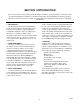
1. Pull bottom trim panel forward to release
from spring catches and lower to full open
position as shown. See Figure 2-4.
2. Remove screws and terminal block cover
(3,2).
3. Bring power supply line in through 1 3/4"
44mm access hole in rear panel and feed
through conduit.
NOTE
If desired, right side panel(s) may be removed
from oven(s) to facilitate connection.
4. Connect line to terminal block. This is a 1/2" 1
3mm conduit connection. Use wire suitable for at
least 90°C.
5. If required, ground unit to ground lug located at
lower right (seen from front) of terminal block.
Consult appropriate electrical codes.
2.4 INSTALLATION CHECK-OUT
After the oven is completely assembled and
properly located with electrical supply connected, the
unit should be given a thorough check-out before
being put into operation. Check-out procedures for
the oven are given in subsection 2.4.1. If the unit fails
to operate as described, consult the trouble-shooting
guide in Section 5 for corrective action.
Before making this check-out, the operator must
be thoroughly familiar with the operating procedures
in Section 3, and with the function of each control
described in Table 3-1. Reference Figure 3-1 for
identification of controls.
2.4.1 Oven Check-Out & Adjustments
Begin check-out procedure with power switch and
thermostat dial in OFF positions. A final check of the
controls and connections should be made as follows:
1. Make sure that the fan guard and deflector
are properly installed. See Figure 6-1.
Figure 2-4 Electrical Connection.
17-0393