
Operating instructions


LIST OF ILLUSTRATIONS
Figure
Page
SECTION 2 INSTALLATION
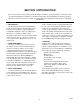
2-1 Counter Stand Assembly 2-2
2-2 Stacked Oven Assembly 2-2
2-3 Open Stand Assembly (Inverted) 2-2
2-4 Electrical Connection 2-3
SECTION 3 OPERATION
3-1 Operating Controls & Indicators 3-2
SECTION 5 TROUBLE SHOOTING
5-1 Wiring Diagram, 208/240 V 5-4
5-1 Wiring Diagram, 440/480 V 5-5
5-3 Wiring Diagram, 220/240/380/415V. 5-6
Figure
Page
e
5-4 Schematic Diagram, 208/240/380 V. 5-7
5-5 Schematic Diagram, 440/460/480 V. 5-8
SECTION 6 MAINTENANCE
6-1 Blower Guard/Deflector Assembly 6-1
6-2 Wheel Puller Kit Components 6-2
SECTION 7 ILLUSTRATED PARTS LIST
7-1 Cabinet & Frame Assembly 7-2
7-2 Door Assembly 7-4
Heating Element Assembly 7-6 7-3
7
-
4
Control Panel Assembly 7-8
LIST OF TABLES
Table Page
SECTION 3 OPERATION
3-1 Operating Controls & Indicators 3-2
Table Page
SECTION 5 TROUBLE-SHOOTING
5-1 Trouble-Shooting Guide 5-1
5-2 Electrical Fault Isolation Guide 5-3
17 0393
IV