
Operating instructions


POWER SAVER II ELECTRIC CONVECTION OVEN
6.3.1.3 Oven Door Horizontal Adjustment
To adjust the doors horizontally (either left to right
or front to back, remove upper and lower trim and
proceed as follows:
1. Loosen the four hex nuts (Figure 7-2, 10)
[two at top and two (not shown) at bottom] on both
doors.
2. Close both doors, and reposition so that doors are
square with top angle and control panel. The gap
between the raised embossments of abutting door
edges should be approximately 1/32" 1mm. It is
important that this gap be maintained the full
height of the doors. Tighten nuts (10).
3. Open each door. Check that inside surface of door
trim contacts raised edge of oven liner at top and
bottom. Readjust if necessary.
4. Replace trim.
6.3.1.4 Oven Door Vertical Adjustment
To adjust the doors vertically:
1. Loosen the two hex nuts (Figure 7-2, 9).
2. Back off top door pivot pin (8).
3. Reposition door by turning bottom door pivot pin
(8). Turn pin clockwise (up) or counter-clockwise
(down) as required. Top of doors should be level
with each other and equally spaced between top
and bottom trim.
4. Retighten the two hex nuts.
5. Replace trim.
6.4.1 Control Panel and Contactor Removal
All controls of the oven are serviceable from the
front. By removing the control panel (Figure 7-1, 14)
all panel components and the contactor mounted
behind the panel are accessible for replacement.
1. Remove screws (Figure 7-1, 22) from control panel
(14).
2. Pull panel forward being careful to avoid damaging
controls and wiring.
WARNING
Controls carry a minimum of 208 volts. Make sure
external circuit breaker supplying power to the
oven is shut off before removing panel.
3. Remove contactor (Figure 7-3, 6) or panel
components identified in Figure 7-4 as required
and reassemble.
6.4.2 Right Side Panel Removal
1. Remove six screws from top panel (Figure 7-1, 11)
on right side.
2. Remove four screws from rear of right side panel.
(2).
3. Remove four screws (22) from control panel. (14).
WARNING
Controls carry 208 volts. Make sure external circuit
breaker is shut off before removing panel, to avoid
accidental shock or short circuit.
4. Remove right side panel.
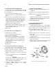
6.4.3 Fan Disassembly and Repair
6.4.3.1 Fan Blade Removal
Removal of the fan requires use of a wheel puller
kit (part #99-3334) supplied by Market Forge. Wheel
puller kit components are shown in Figure 6-2. To
remove fan blade, proceed as follows:
1. Remove deflector and fan guard (Figure 7-1, 18,
17).
2. Remove Allen head set screws which secure fan to
motor shaft.
3. Install wheel puller over hub of fan using Allen
head cap screws.
4. Gradually tighten hex bolt on wheel puller until fan
slides off motor shaft.
5. Remove wheel puller from fan blade and reinstall
replacement fan on motor shaft as required.
Figure 6-2 Wheel Puller Kit Components .
17-0393
6
-
2