
Operating instructions


SECTION 6 MAINTENANCE
6.1 GENERAL
This section contains both preventive and
corrective maintenance information. Preventive
maintenance may be performed by maintenance
personnel at the establishment where the oven is
installed. It is recommended that user personnel
never attempt to make repairs without the assistance
of an authorized service agency. Assistance in
service methods or a current directory of authorized
Service Agencies may be obtained from Market
Forge. (See subsection 1.3).
6.2 PREVENTIVE MAINTENANCE
A good preventive maintenance program in the
form of daily cleaning procedures is outlined in the
following steps. Use mild detergent and water for
washing unless otherwise directed.
1. Remove oven shelves. Wash, rinse and dry.
2. Remove left and right hand shelf supports by lifting
up and out toward center of oven. Wash, rinse and
dry.
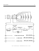
3. Remove deflector and fan guard (Figure 6-1) by
lifting up and out. Wash, rinse and dry.
4. Clean interior sides, bottom and top using stainless
steel cleaner (not polish). Rinse as required and
dry.
5. Replace deflector, fan guard, shelf supports and
shelves.
6. Clean both sides of doors, using a stainless steel
cleaner. Rinse as required and dry.
6.3 ADJUSTMENT PROCEDURES 6.3.1
Oven Door Adjustments
Access to adjustable parts is obtained by first
removing upper oven trim (Figure 7-2 #17), held in
place by screws (1 and 2), and lower trim (34), which
can be pulled forward without removing hardware.
Figure 6-1 Blower Guard/Deflector Assembly.
6.3.1.1 Door Catch Adjustment
1. Loosen door catch assembly mounting screws
(Figure 7-2, 4) at top and bottom of door frame.
2. Move door catch assembly (7) in or out as required
to hold door firmly against oven front. Do not leave
any gaps or space between roller on door catch
assembly and dimple on door trim.
3. Tighten the screws (4) and replace trim.
6.3.1.2 Door Switch Adjustment
If convector fan fails to turn on when the right-side
oven door is closed and power is on (circuit breaker
and ON-OFF switch in ON positions) the door switch
may require adjustment. With upper trim removed
switch (Figure 7-2, 20) is fully exposed. Adjustment is
made by bending the actuator arm until correct
operation is obtained.
1. Bend lever to left (away from switch) to shorten
switch action throw. Bend right to lengthen throw.
2. Open and close door several times to check switch
adjustment. Repeat step 1 as required to obtain
proper ON-OFF operation of con-vector fan.
3. Replace upper trim (17).
6
-
1
17
-
0393