
Operating instructions


TROUBLE SHOOTING 53
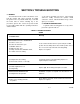
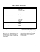
TABLE 5-2 ELECTRICAL FAULT ISOLATION
FAILURE FAULT LOCATION
1 Oven will not operate when thermostat is set.
a. Incoming power
b. Door switch
c. Thermostat control
d. ON-
OFF switch
e. Circuit breaker
f. Contactor
g. Wiring
2 Intermittent operation of heaters. a. Thermostat control
b. Contactor coil
c. Wiring
3. Convector fan fails to operate. a. Circuit breaker
b. ON-
OFF switch
c. Door switch
d. Fan motor
e. Wiring
4. Indicator light off, (heater under power).
a. Indicator light
b. Wiring
5 Uneven heating. a. Heating elements
b. Wiring
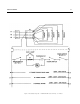
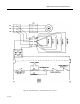
5.4.4 Wiring
All the electrical components of the Power Saver II
(ON-OFF switch, door switch, thermostat control,
contactors, circuit breaker, fan motor, and indicator
light) are connected to each other by wiring shown in
figures 5-1, 5-2, or 5-3. If all the electrical components
are operating correctly and the incoming power has
been checked, but the unit fails to operate, the fault
lies in the wiring.
Using an ohmmeter, wiring continuity between the
connections, shown on the wiring diagrams, is readily
verified. This is best done in stages, removing only
those wires required for each continuity check. As
each lead is replaced, it should be checked for
evidence of corrosion and cleaned if necessary. All
leads must be tightly attached to provide a good
electrical connection.
17-0393