
Operating instructions


52 POWER SAVER II ELECTRIC CONVECTION OVFN
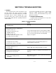
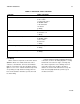
5.3 ELECTRICAL FAULT ISOLATION
Correction of an electrical fault first requires
isolation of the fault to a single circuit or component
In most cases, the nature of the failure and its effect
upon the operation of the oven will he sufficient to
isolate it to one or more circuit elements Table 52 is
provided as a guide for isolating electrical faults
5.4 ELECTRICAL TROUBLE SHOOTING
PROCEDURES
Before performing the trouble-shooting pro-
cedures in this section, the servicer must be familiar
with the function of all controls as described in
Section 3 and the Principles of Operation described
in Section 4.
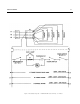
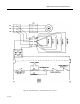
Electrical trouble-shooting procedures which
follow require access to components and terminals
of the operating controls. Electrical controls are
reached by removing the control panel as described
in paragraph 6.4.1. Wiring and terminal locations are
shown in figures 5-1, 52, and 5-3 Figures 54 and 5-5
show the circuits in schematic form.
5.4.1 Incoming Power
Before trouble-shooting any of the electrical
parts or assemblies, make sure power is being
supplied to the terminal block (figure 7-3, 8A).
With power connected to the oven an a-c voltmeter
is used to measure 208 or 240 volts (depending on
the oven model) across terminals. Make sure the
unit is properly grounded to the ground lug beside
the terminal block. If the proper voltage (as noted on
the unit rating plate) is present, the fault lies in the
electrical circuits of the oven
5.4.2 Electrical Inspection
The first step in any electrical trouble-shooting
procedure is a thorough inspection of all wiring
connections. To access the electrical components,
remove panel as described in subsection 6 4.1
WARNING
Before removing the control panel or checking
connections or wiring, make sure incoming
power is shut off. When power is supplied, all
exposed terminals carry at least 208 volts.
Check all connections by hand to ensure that all
connection points are tightly secured. Use a
screwdriver to tighten if necessary Inspect all quick-
disconnect terminals for evidence of corrosion.
Terminals in this condition should be replaced.
5.4.3 Thermostatic Control
5.4.3.1 Thermostat Contacts
Defective contacts will result in failure of the oven
to operate properly. If the oven fails to heat when the
thermostat knob is set to the desired temperature, the
fault may be the thermostat switch contacts or
thermostat wiring. When this occurs, remove the
control panel (subsection 6.4.1) and proceed as
follows:
1. Turn off power to the oven at circuit breaker
2. Disconnect all wires from thermostat terminals.
(See Figures 5-1, 5-2, and 5-3).
3. Rotate the thermostat knob to the maximum
setting. With the oven cool, a zero ohm reading
should be obtained on the ohmmeter. If zero
reading cannot be obtained, contacts are defective
and the thermostat must be replaced.
4. Remove ohmmeter and replace all leads on
terminals as shown on appropriate wiring diagram.
5.4.3.2 Thermostat Capillary
A defective or punctured capillary/bellows system
may cause continuous operation of the elements. If
continuous operation occurs and recalibration of the
thermostat as explained in subsection 6.3.2 fails to
correct the problem, the entire thermostat control
must be replaced.
170393