
Operating instructions


SECTION 4 PRINCIPLES OF OPERATION
4.1 GENERAL
The Power Saver II electric convection oven uses a
carefully designed insulation system, which achieves
optimal cooking heat from power consumed. A
convector fan distributes heated air uniformly
throughout the oven interior. Heat is supplied by
electric elements, controlled by a thermostat mounted
on the control panel.
4.2 HEATING CIRCUITS
With electrical power available, power switch on,
doors closed and thermostat set, a circuit is closed to
a contactor mounted behind the oven controls. This
contactor in turn closes, supplying power to the oven
heating elements, located beneath and at the rear of
the cooking chamber.
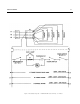
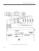
4.3 ELECTRICAL CIRCUITS AND CONTROLS
Input power is connected at the terminal block
mounted at the right front of the oven, behind the
hinged lower trim. The control circuit is shown in the
schematic drawings. Figures 5-4 & 5-5. They show the
relationship of each control and the sequence of
operation. A brief description of major electrical circuit
components is included in the following paragraphs.
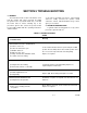
4.3.1 Circuit Breaker
A 15 Amp circuit breaker located at the bottom of
the control panel provides overload protection for the
208/240 volt branch circuit to controls. Input
connection is made from L1 and L3 for 3-phase
connection, L1 and L2 for single-phase, and N and L3
for four-wire, 3-phase. It feeds power to the poles of
the power switch.
4-1 17 0393
4.3.2. ON-OFF Switch
Control of power to the oven control circuits is
provided by the ON-OFF Switch. It is a double-pole,
double-throw toggle switch connected between the
circuit breaker and the door switch.
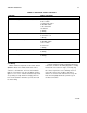
4.3.3 Door Interlock Switch
The door interlock switch is a single pole, two
position microswitch with normally open contacts. The
switch lever is operated by an actuating bar built into
the door jamb of the right side door. When the door is
open, the bar remains retracted with the switch
contacts in the normally open position. When the door
is closed, the door pushes the actuating bar against
the switch lever to close the contacts. Connected into
the circuit for the fan and thermostat, the door switch
interrupts fan operation and deactivates the heating
circuits when the door is opened.
4.3.4 Thermostat Control
The thermostat is a bulb and capillary type system,
manually adjustable from 200-475°F 94-246°C. The
oven is put into an automatic heating cycle with the
setting of the thermostat to any of its calibrated
temperature settings. Expansion and contraction of
gas within the capillary/bellows system in response to
temperature change opens and closes the thermostat
contacts, energizing and deenergizing the heating
element circuit.
4.3.5 Indicator Light
The Indicator Light is wired to operate only when
the circuit is completed through the thermostat control
to the coil of the heater contactor. It is on only when
the heating elements are under power.