SERVICE & PARTS MANUAL Power Saver II Electric Convection Oven Models: 2600HE 2692HE 2800HE 2892HE MARKET FORGE CANADA LTD.
TABLE OF CONTENTS Paragraph SECTION 1 INTRODUCTION 1.1 Description 1.2 Oven Components 1.3 Basic Functioning 1.4 Service SECTION 2 INSTALLATION 2.1 Receiving 2.2 Assembly 2.2. 1 Single Oven On Modular Base 2.2.2 Oven On 7"{178mm) Stand 2.2 3. Stacked Ovens On 7" (178mm) Stand 2.2.4 Oven on 28"( 711 mm) Open Stand 2.3 Electrical Connection 2.4 Installation Check-Out 2.4.1 Oven Check Out & Adjustments 2.4.
LIST OF ILLUSTRATIONS Figure Page Figure 5-4 Schematic Diagram, 208/240/380 V. Page e 5-7 2-1 Counter Stand Assembly 2-2 Stacked Oven Assembly 2-3 Open Stand Assembly (Inverted) 2-4 Electrical Connection SECTION 3 OPERATION 2-2 2-2 2-2 2-3 5-5 Schematic Diagram, 440/460/480 V.
SECTION 1 INTRODUCTION This service and parts manual contains general information, installation, operation, principles of operation, troubleshooting and maintenance information for the Market Forge Power Saver II High Efficiency Electric Convection Oven. Also included are parts lists, in which each replaceable part is identified and shown in an accompanying exploded view. 1.1 DESCRIPTION circuit to heating elements located underneath and at the rear of the cooking chamber.
SECTION 2 INSTALLATION 2.1 RECEIVING The unit is shipped strapped and bolted to a skid, and covered by a corrugated container. Packing materials must be removed prior to installation Examine shipment for external or internal damage and completeness. A complete shipment normally includes the oven unit, two shelf supports and five interior shelves, a carton containing stand components (if a stand has been specified), and a packet of documents pertaining to the unit.
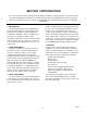
2-2 POWER SAVER II ELECTRIC CONVECTION OVEN Figure 2-1 Counter Stand Assembly . Figure 2-2 Stacked Oven Assembly .
INSTALLATION 23 supports (if supplied), inserting ends through holes in clips and shelf. 8. Mount oven to stand using four 3/8 - 1 6 x 3/4 Ig. hex head cap screws and four 3/8 plain washers provided. 2.3 ELECTRICAL CONNECTION Where applicable, all wiring shall be done in accordance with the Canadian Electrical Code ANSI C1 - 1975. Figures 5-1, 5-2 and 5-3 show the various internal wiring configurations for the different models and voltages. 1.
POWER SAVER II ELECTRIC CONVECTION OVEN 24 2. Seat wire shelf supports in mounting locations inside oven, and slide shelves into position with raised 'stop' edge at rear. NOTE Make sure wire shelf supports are in, not on, brackets 3. With a level on the oven shelves, make sure the oven is level both front and back, left and right To adjust, turn feet in stand legs. 4. Make sure power supply is available to the oven 5. Set thermostat dial at 350°F. 6. Place power switch in the ON position with doors open 7.
SECTION 3 OPERATION 3.1 OPERATING CONTROLS AND INDICATORS All the controls required to operate the oven are listed in Table 3-1, with a short functional description of each. Figure 3-1 shows the physical location of each control and indicator. 3.2 OPERATING PROCEDURES Before attempting to use the oven for cooking, be sure that proper electrical connections have been made, and fan guard and deflector are properly mounted. (See Figure 6-1). 3.2.1 Preheating 1.
POWER SAVER II ELECTRIC CONVECTION OVEN 3-2 TABLE 3-1 OPERATING CONTROLS AND INDICATORS FIG. 3-1 REF. DESCRIPTION FUNCTION Thermostat Control Regulates oven temperature. Controls heating element operation. 2 60-Minute Timer Electric timer to aid operator in timing cooking cycle. Does not control oven operation. 3 5-Hour Timer Same as 60-Minute Timer. ON-OFF Switch Controls electrical power to thermostat and fan motor. Must be in ON position for oven to operate.
SECTION 4 PRINCIPLES OF OPERATION 4.1 GENERAL 4.3.2. ON-OFF Switch The Power Saver II electric convection oven uses a carefully designed insulation system, which achieves optimal cooking heat from power consumed. A convector fan distributes heated air uniformly throughout the oven interior. Heat is supplied by electric elements, controlled by a thermostat mounted on the control panel. Control of power to the oven control circuits is provided by the ON-OFF Switch.
SECTION 5 TROUBLE-SHOOTING 5.1 GENERAL The information in this section is intended to assist both the operator and service personnel in locating the general source of problems which may occur with the Power Saver II. Before following any of the procedures given in this section, the operator should be thoroughly familiar with the operating instructions and the function of all controls described in Section 3.
52 POWER SAVER II ELECTRIC CONVECTION OVFN 5.3 ELECTRICAL FAULT ISOLATION WARNING Before removing the control panel or checking connections or wiring, make sure incoming power is shut off. When power is supplied, all exposed terminals carry at least 208 volts.
TROUBLE SHOOTING 53 TABLE 5-2 ELECTRICAL FAULT ISOLATION FAILURE FAULT LOCATION 1 Oven will not operate when thermostat is set. a. Incoming power b. Door switch c. Thermostat control d. ON-OFF switch e. Circuit breaker f. Contactor g. Wiring 2 Intermittent operation of heaters. a. Thermostat control b. Contactor coil c. Wiring 3. Convector fan fails to operate. a. Circuit breaker b. ON-OFF switch c. Door switch d. Fan motor e. Wiring 4. Indicator light off, (heater under power). a.
FIG .
Troubleshooting 5-5 55 Figure 5-2.
5-6 Power Saver II Electric Convection Oven Figure 5-3. Wiring Diagram — 220/240/380/415 Volt, 50/60 Hz.. 3 Phase.
TROUBLE SHOOTING 5-7 Figure 5-4 Schematic Diagram — 208/240/380/415 Volt, 50/60 Hz..
5-8 POWER SAVER II ELECTRIC CONVECTION OVEN Figure 5-5. Schematic Diagram — 440/460/480 Volt, 60 Hz., 3 Phase.
SECTION 6 MAINTENANCE 6.1 GENERAL This section contains both preventive and corrective maintenance information. Preventive maintenance may be performed by maintenance personnel at the establishment where the oven is installed. It is recommended that user personnel never attempt to make repairs without the assistance of an authorized service agency. Assistance in service methods or a current directory of authorized Service Agencies may be obtained from Market Forge. (See subsection 1.3). 6.
6-2 POWER SAVER II ELECTRIC CONVECTION OVEN 6.3.1.3 Oven Door Horizontal Adjustment To adjust the doors horizontally (either left to right or front to back, remove upper and lower trim and proceed as follows: 1. Loosen the four hex nuts (Figure 7-2, 10) [two at top and two (not shown) at bottom] on both doors. 2. Close both doors, and reposition so that doors are square with top angle and control panel. The gap between the raised embossments of abutting door edges should be approximately 1/32" 1mm.
MAINTENANCE 6-3 6.4.3.2 Fan Motor Removal 6.4.4.2 Bottom Heating Element Removal Motor removal is completed from inside the oven With external circuit breaker shut off, proceed as follows 1 Remove deflector and fan guard (Figure 71, 18,17) 2. Remove four nuts (20) and clips (19, 21 and 23) from motor assembly. 3. Pull motor forward. Carefully disconnect electrical wiring. 4. Slide motor off screws. Identify and tag wires. 5.
SECTION 7 ILLUSTRATED PARTS LIST 7.1 General This section contains a complete listing of all replaceable parts of the Power Saver II Electric Convection Oven. For the purpose of parts identification, the unit is broken down into functional assemblies, and each assembly is shown in an exploded view which is keyed to the accompanying parts list. Each parts list contains the figure index number, the Market Forge part number, and an abbreviated description. 7.
Power Saver II Electric Convection Oven 7-2 Figure 7-1 Cabinet & Frame Assembly .
ILLUSTRATED PARTS LISTS 7-3 Fig. 7-1 Item No. Part No. Description 1A 1B 2A 99-1681 99-1572 99-3327 Rear Panel, stainless steel Rear Panel, enamel Side Panel, right, 33" standard oven.
7-4 POWER SAVER II ELECTRIC CONVECTION OVEN Figure 7-2 Door Assembly .
ILLUSTRATED PARTS LISTS 7-5 Fig. 7-2 Item No. Part No. Description 1 2 3 4 5 6 10-1717 10-1956 10-2341 10-1759 10-2509 10-2432 Screw, rnd. hd., #8-32 x 3/8" Ig. Screw, Phillips truss hd., #10-32 x 3/8" Ig, Washer, #10, thin Screw, rnd. hd., #10-32 x 3/8" Ig.
7-6 POWER SAVER II ELECTRIC CONVECTION OVEN Figure 7-3 Heating Element Assembly .
ILLUSTRATED PARTS LISTS Fig. 7-3 7-7 Part No. Description Item No.
7-8 POWER SAVER II ELECTRIC CONVECTION OVEN Figure 7-4 Control Panel Assembly . Fig. 7-4 Item No. 1 2 3 4 5 6 7 8 9 10 11 12 13 14 17-0393 Part No. Description 10-6415 10-6307 99-4561 10-4714 10-5520 10-5553 10-6669 10-7903 10-6280 10-6521 10-1979 10-2541 10-1836 10-2332 Bezel, panel Knob, control Nameplate, 60Hz panel Thermostat Timer, 60-minute Timer, 5-hour Indicator Light, red Toggle Switch, OFF/ON Circuit Breaker, 15 Amp Mounting Plate, circuit breaker Screw, flat hd.