
Operating instructions


6
InstallatIon
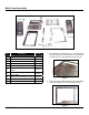
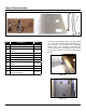
Oven Cavity Assembly
Figure 8
Item Description Part No.
1 Split Liner Top 98-3576
2
Split Liner Bottom (Has 2 Crease
Lines)
98-3655
3 U-Shaped Split Liner Gasket (2) 98-1796
4 Split Liner Rear 98-3579
5 Split Liner Left 98-3577
6
Split Liner Right (Has Slots in Corner
for Heating Element)
98-3578
7 Vertical Split Liner Gasket (2) 98-1797
8 Cavity White Insulation (2) 15-7561
9 Insulation Straps with Clips (2)
10 Rear Cavity Insulation (Not Shown) 98-3613
11
Top Cavity Insulation 1.5” Thick (Not
Shown)
98-3619
NOTE: 15 parts total
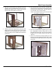
1. Lay the split liner bottom (2) at and place the U-
shaped split iner gasket (3) around the split liner bot-
tom.
Figure 9
2. Bolt on loosely the split liner rear (4) to the split liner
bottom using 1/4-20 hex bolts. Then put the vertical
split liner gasket (7) hanging on the top bolt of the left
and right side.
Figure 10
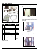
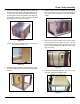
3. Bolt the split liner left (5) and split liner right (6) to the
split liner bottom and split liner rear.
NOTE: The split liner right has holes in it for the heat-
ing element.
Figure 11