
Operating instructions


14
InstallatIon
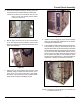
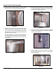
Inside Oven Cavity Assembly
2. Install the element support bracket (4), which will be
to the left of the fan, using two self-taping screws.
Figure 36
3. Install the grommet (7) on the right side of the cavity.
Then punch a hole through the grommet and CARE-
FULLY unwind the thermostat capillary tube located
behind the front control panel and feed it through the
grommet and into the cavity.
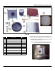
Run the capillary tube along the top of the cavity to
the back and down through the thermostat brackets.
Use capillary clips (6) to fasten the tube using self-
taping screws.
Figure 37
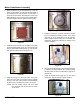
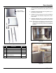
4. Place the element gasket (9) on the heating element
(1) and install using four allen set screws. Bolt down
the element using #8-32 keps nuts.
Figure 38
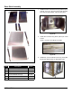
5. Connect the heating element to the proper cables as
indicated in the wiring diagram located in Appendix A
of this manual (6 wires).
Figure 39
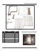
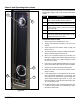
6. Attach the bafe (2) and side racks (8) to the inside of
the oven cavity as shown. Use four ¼”-20 shoulder
bolts for the bafe.
Figure 40