
Operating instructions


9
InstallatIon
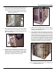
Control Panel Assembly
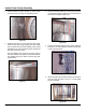
2. Attach the reed switch bracket (9), which is part of the
control panel to the insulation/electric panel divider.
NOTE: The position of the reed switch must be such
that it is in the most forward position relative
to the front of the oven.
Figure 21
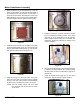
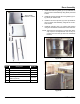
3. Bolt the green ground wire of the front control panel
(1) to the frame as seen in the picture. Use a #10-32
keps nut to fasten to the stud located behind the front
frame weld assembly.
Figure 22
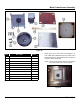
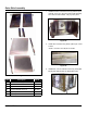
4. Fasten the front control panel to the front frame weld
assembly using four #8-32 pan head screws, one in
each corner of the control panel face. Then attach
the electric control panel (2) to the insulation/electric
panel divider using three self-taping screws.
Figure 23
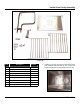
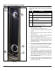
5. Install 2 conduit couplings (5) on the conduit raceway
tubing (4) and install this combination to the electric
control panel and junction box.
6. Then install the exible conduit tubing for the high lim-
it thermostat (7), motor (6), and transformer (6). The
high limit thermostat has two lead wires that are white
and is positioned through the third hole down from the
top of the frame liner support/back channel. Do the
same for the motor which has three wires numbered
45, 46 and 52.Then again for the transformer, which
has four wires numbered 36, 37, 38 and 39 where the
transformer conduit is on the bottom of the three.
Figure 24
NOTE: The tubing for the thermostat is 12” while the mo-
tor and transformer is 32”.