MSA-SB-2600 MILITARY SUB-ASSEMBLY HIGH EFFICIENCY ELECTRIC CONVECTION OVEN INSTALLATION - OPERATION - service - parts models MSA-SB-2600 MSA-SB-2692 NSN: 9Z 7310-01-519-8399 APL: 43A040025 MF P/N: 98-3600 (No Drain) NSN: TBD APL: TBD MF P/N: 98-3660 (Liner Drain) 44 Lakeside Avenue, Burlington, Vermont 05401 USA Telephone: (802) 658-6600 Fax: (802) 864-0183 www.mfii.com PN 14-0395 Rev a (9/14) © 2014 - Market Forge Industries Inc.
TABLE OF CONTENTS IMPORTANT WARNING: Improper installation, adjustment, alternation, service or maintenance can cause property damage, injury or death. Read the installation, operation and maintenance instructions thoroughly before installing or servicing this equipment. FOR YOUR SAFETY Do not store or use gasoline or other flammable vapors or liquids in the vicinity of this or any other appliance. INSTALLATION Introduction.. . . . . . . . . . . . . . . . . . . . . . . . . . . . . . . . . . . . . . . . .
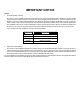
IMPORTANT NOTICE NOTES 1. Accutemp griddle mounting; This version of the Installation Manual for the Market Forge oven model MSA-SB-2600 includes the (4) parts (listed below) that were modified in order to accept the Accutemp Griddle being mounted on top. All ovens shipped from the Market Forge factory with a Serial Number less than #226167 will require a back fit kit, Market Forge part number 984162, in order to mount the Accutemp griddle.
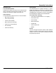
Introduction YOUR ENERGY EFFICIENT CONVECTION OVEN HOW THE OVEN OPERATES MSA-SB-2600 convection ovens are electrically powered, high capacity ovens featuring high energy efficiency. These ovens are designed to radically cut power consumption, delivering the cooking power of a 16 KW oven from only 11 KW’s of energy input. Improvement of energy use is made possible by a carefully designed insulating system which keeps heat inside the oven longer.
Assembly Instructions INTRODUCTION Time Estimate The model MSA-SB-2600: The estimated time for complete assembly is approx- mately 6-7 hours for a first timer or 4-5 hours for an experienced assembler. The oven assembly can be completed with one person, but for a more productive assembly two people are recommended. Submarine-Accessible Convection Oven contains 88 total parts for assembly and is designed such that it can be assembled in a submarine’s galley with simple tools.
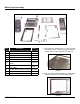
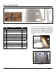
Main Frame Assembly Figure 3 Item Description 1. Bolt together the split base front (1) to the split base rear (2) using seven ¼-20 hex bolts. Then fasten the Junction Box (11) to the split base rear using nuts. Part No.
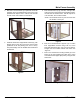
Main Frame Assembly 3. Bolt Rear U-channel frame (3) to split base front/ rear assembly. There are welded bolts in the corner of the split base rear. Slip the rear u- channel over the bolts and use a two nuts to fasten it to the frame. 5. Bolt channel frame top (6), left side, and right side, front to back (7) to the Frame liner support/back channel and Rear U-channel frame. This will require six ¼-20 hex bolts, two for each member.
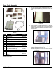
Oven Cavity Assembly 1. Lay the split liner bottom (2) flat and place the Ushaped split iner gasket (3) around the split liner bottom. Figure 9 2. Bolt on loosely the split liner rear (4) to the split liner bottom using 1/4-20 hex bolts. Then put the vertical split liner gasket (7) hanging on the top bolt of the left and right side. Figure 8 Item Description Part No.
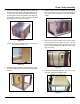
Oven Cavity Assembly 4. Then place another U-shaped split liner gasket (3) around the top and finish by bolting the split liner top (1) to the rest of the cavity. Now fasten each and every bolt without moving the gaskets. Then apply silicon sealant to areas of need. As a reminder the front face flanges of the cavity must be flush. 6. Install the whole cavity to the mainframe and secure with four #8-32 S.S hex nuts to the weld studs on the corners of the cavity thru the front frame weld assembly.
Control Panel Assembly Figure 20 Item Description 1. Bolt on the Inner insulation panel mounting bracket (11) to the inner insulation/electric panel divider (3) and then fasten it to the Frame liner support/back channel using three self-taping screws.Then fasten the nuts on the inner insulation panel mounting bracket where it sleeves over the front frame weld assembly. Part No.
Control Panel Assembly 2. Attach the reed switch bracket (9), which is part of the control panel to the insulation/electric panel divider. NOTE: The position of the reed switch must be such that it is in the most forward position relative to the front of the oven. Figure 23 Figure 21 5. Install 2 conduit couplings (5) on the conduit raceway tubing (4) and install this combination to the electric control panel and junction box. 3.
Control Panel Assembly 7. Attach the high limit thermostat-mounting bracket (8) to the Frame liner support/back channel using two self-taping screws. 8. Connect the high limit thermostat (10) to the two lead wires and then fasten to the inside of the cavity using two #6-32 screws.
Motor Transformer Assembly Figure 28 Item Description 1. Attach motor (2) to the motor mount bracket (1). Then install this combination from the inside of the cavity with the motor wires positioned on the top. Do not bolt to cavity at this point. Part No.
Motor Transformer Assembly 2. Place the white motor mount insulation (11) over the motor mount bracket. Tuck the left and right sides of the insulation down into the space on both sides of the motor mount bracket. Then place the motor cover plate gasket (5) over the motor mount gasket (placement is important since the gasket is NOT square). Figure 31 5. Install the transformer (3) where the bottom will slot into the transformer-mounting bracket.
Inside Oven Cavity Assembly Figure 35 Item Description 1. Install the vent tube (3) using four self-taping screws. Then install the side rack clips (5), four on each side of the oven and use two self-taping screws per clip. Part No.
Inside Oven Cavity Assembly 4. Place the element gasket (9) on the heating element (1) and install using four allen set screws. Bolt down the element using #8-32 keps nuts. 2. Install the element support bracket (4), which will be to the left of the fan, using two self-taping screws. Figure 36 Figure 38 3. Install the grommet (7) on the right side of the cavity.
Door Assembly 1. Install horizontal liner gasket (6) on top andbottom of the front frame weld assembly using #8-32 pan head screws. Door Handle Part No. 10-0657 2. Install left and right vertical door liner gaskets (5) using #8-32 pan head screws. 3. Install the two door top latch (3) in the top-middle of the front frame weld assembly using #8-32 countersunk screws. 4. Install left and right door (1-2). Fasten door bearing using #10-32 flat head countersunk screws and nuts.
Outer Skin Assembly 1. Install the bottom u-channel cover (2) and the top Uchannel cover (3) to the front frame weld assembly. No screws or bolts needed. Just pop in the parts. Figure 45 2. Install door lock latch using #8-32 quarter pan head screws. NOTE: Close door and adjust as needed. Figure 46 3. Install two, corner channel cover’s (4) using two #8-32 pan head screws on the bottom only. Figure 44 Item Description Part No.
Outer Skin Assembly 4. Have an electrician wire a power supply line through the raceway conduit rates at 480 VAC, 3 Phase. 5. Install the side frame skin (1) on the right and left side of the oven. Use one #8-32 pan head screw per side. Figure 48 6. Install the split top cover (5) and screw the rear corner to the corner channel using two #8-32 pan head screws per corner. 7. Lastly install the split top front (6) and fasten to the split rear using seven #8-32 quarter pan head screws.
Control and Operating Instructions The controls required to operate the oven are listed in the following table together with a short functional description of each. 1 2 Item Description 1 Thermostat Control - Regulates oven temperature. Controls heating element operation. 2 Thermostat Light - Indicates when the thermostat is calling for heat and the elements are ON. 3 Timer/Constant Heat - Electrical timer to aid in time cooking cycles. Controls oven and constant heat mode.
Cleaning A good preventive maintenance program in the form of daily cleaning procedures is outlined in the following steps: 1. Remove oven shelves and wash in mild detergent and water. Rinse and dry. 2. Remove left and right hand shelf supports by lifting up and out toward center of oven. Wash, rinse and dry. 3. Remove fan baffle by lifting up and out. Wash, rinse and dry. 4. Wash interior sides, bottom, and top with mild detergent and water.
Troubleshooting PROBLEM Probable Cause REMEDY CONVECTOR FAN FAILS TO OPERATE Power to oven is off. Locate external circuit breaker for power and place in ON position. Power switch off. Place in ON position. Right oven door open. Close Door. Control circuit breaker off. Place in ON position. Faulty circuit breaker, door interlock switch, fan motor, or Refer to wiring diagram or obtain outside service. wiring.
Wiring Diagram Figure 51 21 maintenance
Recommended Spare Parts Part No. Description Qty.
Door Assembly with Slide Latch 1A 2 4 5 11 6 1A 12 13 Kit #98-3694 14 6 15 5 2 4 3 1 7 Note: Kit #98-3694, Parts Not Sold Separately. 3 10 8 9 1 1A Figure 52 Item Part No.
Control Panel with Probe Option Figure 53 Item Part No.
Control Panel with Probe Option Figure 54 Item Part No.
Oven Performance Verification Check List 5. Verify that the racks do not bind at 400°F. 1. Verify that the doors are properly aligned and that there is no interference occuring at room temperature and 400oF. 2. Verify that all screws and bolts are tight. Verify the accuracy of the oven’s thermostat at 350°F by comparing the temperature control setting to the temperature at the center of the oven (one thermocouple). The maximum difference is to be no more than +/- 5°F. 3.
Spec Information MODEL: MSA-SB-2600 OPTIONAL AT EXTRA COST: SIZE: • Extra shelves_______quantity. • Meat Probe/Thermometer. • 1 3/4” Diameter Liner Drain. • Legs (4) with Flanged Feet (3/4-10” Thread). 35-1/4” Deep x 36” Wide x 25-1/4” High (896mm Front-to-Back x 914mm Wide x 641mm Top-to-Bottom) DESCRIPTION: Will be a Market Forged Military SubAccessible High Effiiency Electric Convection Oven equipped with COOK & CONSTANT COOK controls.
Spare Parts List Description Part No.
Parts List Fasteners Length (inches) Thread Size Qty SCREW CAP HEX HEAD 0.5 1/4”-20 77 10-1814 SCREW CAP HEX HEAD 0.75 1/4”-20 7 08-7840 NUT, SERRATED FLANGE 1/4”-20 73 08-7995 BOLT, HEX HEAD 5/16”-18 4 08-7956 NUT, SERRATED FLANGE 5/16”-18 8 10-2045 SCREW CAP HEX HEAD 0.5 #10-32 2 08-7996 TEK SCREW PHILLIPS PAN HEAD #2 0.5 #10-16 10 10-2146 SCREW, SLOTTED PAN HEAD 0.