
User Guide

Model 3i Digital Force/Torque Indicator User’s Guide
2
1 OVERVIEW
1.1 List of included items
Qty.
Part No.
Description
1
12-1049
Carrying Case
1
08-1022
AC adapter body with US, EU, or UK prong
1
08-1026
Battery (inside the indicator)
1
-
Certificate of calibration
1
09-1165
USB cable
-
USB driver, MESUR
®
Lite software, MESUR
®
gauge evaluation software, User’s Guide
Download at:
www.mark-10.com/resources
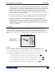
1.2 General Overview
The 3i is a universal indicator designed for displaying
measurements from interchangeable mark-10 Plug &
Test
®
sensors. Sensor capacities are available from
0.25 to 10,000 lbF (1 N to 50 kN) of force, and from
10 ozFin to 5,000 lbFin (7 Ncm to 550 Nm) of torque.
These sensors can be handheld or mounted to a
fixture or test stand for more sophisticated testing
requirements.
Plug & Test
®
sensors are used with the 7i, 5i, or 3i
indicators. They may be disconnected from one
indicator and connected to another without the need
for re-calibration or re-configuration. All such data is
saved within a PCB located inside the smart
connector.
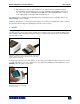
The model number, serial number, and capacity of
the sensor are identified in the rectangular label
located on the Plug & Test
®
connector. The model
and serial numbers are also identified in the Information screen of the indicator.
1.3 Accuracy and Resolution
Indicator accuracy must be combined with sensor accuracy to determine the total accuracy of the system.
Since sensors may be used with the 7i, 5i or 3i indicators, the accuracy of the indicator being used must
be identified and taken into account, as follows:
Indicator Model
Accuracy
3i
±0.2% of full scale
5i / 7i
±0.1% of full scale
The total system accuracy can be calculated by adding the sensor accuracy and indicator accuracy.
Refer to the following examples:
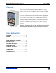
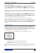
From left to right: Model 5i indicator with Series R01 force
sensor, Model 3i indicator with Series R02 force sensor, and
Model 7i indicator with Series R50 torque sensor