Model 3i DIGITAL FORCE / TORQUE INDICATOR User’s Guide
Model 3i Digital Force/Torque Indicator User’s Guide Thank you… Thank you for purchasing a Mark-10 Model 3i digital force / torque indicator, designed for use with interchangeable remote force and torque sensors. A 3i-sensor combination can be used with some Mark10 test stands grips, and data collection software. With proper usage, we are confident that you will get many years of great service with this product.
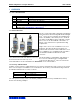
Model 3i Digital Force/Torque Indicator User’s Guide 1 OVERVIEW 1.1 List of included items Qty. 1 1 1 1 1 - Part No. Description 12-1049 Carrying Case 08-1022 AC adapter body with US, EU, or UK prong 08-1026 Battery (inside the indicator) Certificate of calibration 09-1165 USB cable USB driver, MESUR® Lite software, MESUR®gauge evaluation software, User’s Guide Download at: www.mark-10.com/resources 1.
User’s Guide Model 3i Digital Force/Torque Indicator Example 1 Model RTQ50-50Z sensor with Model 3i Indicator MR50-50Z ±0.35% of full scale + 3i ±0.2% of full scale = Total ±0.55% of full scale = Total ±0.25% of full scale This translates into a fixed error of up to: 0.55% x 50 ozFin = 0.275 ozFin Example 2 Model MR01-100 sensor with Model 5i Indicator MR01-100 ±0.15% of full scale + 5i ±0.1% of full scale This translates into a fixed error of up to: 0.25% x 100 lbF = 0.
Model 3i Digital Force/Torque Indicator User’s Guide 8. Typical materials able to be tested include many manufactured items, such as springs, electronic components, fasteners, caps, films, mechanical assemblies, and many others. Items that should not be used with the sensor include potentially flammable substances or products, items that can shatter in an unsafe manner, and any other components that can present an exceedingly hazardous situation when acted upon by a force.
Model 3i Digital Force/Torque Indicator User’s Guide 5. When battery life drops to approximately 2%, the indicator from step 4 will be flashing. Several minutes after (timing depends on usage and whether the backlight is turned on or off), a message appears, “BATTERY VOLTAGE TOO LOW. POWERING OFF”. A 4-tone audio indicator will sound and the indicator will power off. The indicator can be configured to automatically power off following a period of inactivity.
Model 3i Digital Force/Torque Indicator User’s Guide 3.2 Mounting to a plate The 3i can be mounted to a plate with four thumb screws fastened into the appropriate holes in the rear half of the housing. Refer to the Dimensions section for detailed hole information and locations. 3.4 Installing the USB driver If communicating via USB, install the USB driver available at: www.mark-10.com/resources Caution! Install the USB driver before physically connecting the indicator to a PC with the USB cable.
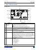
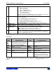
User’s Guide Model 3i Digital Force/Torque Indicator 4 HOME SCREEN AND CONTROLS 4.1 Home Screen 1 9 2 8 3 4 7 6 No. 1 Name Measurement direction indicator 2 Peaks 3 Primary reading 4 Load bar 5 Units 5 Description – indicates compression direction (for force sensors) – indicates tension direction (for force sensors) – indicates clockwise direction (for torque sensors) – indicates counter-clockwise direction (for torque sensors) These indicators are used throughout the display and menu.
User’s Guide Model 3i Digital Force/Torque Indicator 6 Mode 7 Battery / AC adapter indicator High / low limit indicators 8 9 Set points Torque units: lbFin – Pound-inch ozFin – Ounce-inch kgFm – Kilogram-meter kgFmm – Kilogram-millimeter Nm – Newton-meter Ncm – Newton-centimeter Note: not all sensor models display all the above units. Refer to the capacity / resolution table for the respective sensor series for details. The current measurement mode.
Model 3i Digital Force/Torque Indicator User’s Guide 4.3 Menu navigation basics Most of the indicator’s various functions and parameters are configured through the main menu. To access the menu press MENU. Use the UP and DOWN keys to scroll through the items. The current selection is denoted with clear text over a dark background. Press ENTER to select a menu item, then use UP and DOWN again to scroll through the sub-menus. Press ENTER again to select the sub-menu item.
User’s Guide Model 3i Digital Force/Torque Indicator 6 SET POINT INDICATORS 6.1 General Information Set points are useful for tolerance checking (pass/fail). Two limits, high and low, are specified and stored in the non-volatile memory of the instrument and the primary reading is compared to these limits. 6.2 Configuration To configure set points, select Set Points from the menu. The screen appears as follows: SET POINTS Upper Disabled * Upper Enabled 5.00 Lower Disabled * Lower Enabled 3.
Model 3i Digital Force/Torque Indicator User’s Guide 7.2 Peak Compression (PC) / Peak Clockwise (PCW) - for force / torque sensors, respectively The primary reading corresponds to the peak compression or clockwise reading observed. If the actual load decreases from the peak value, the peak will still be retained in the primary reading area of the display. Pressing ZERO will reset the value. 7.
Model 3i Digital Force/Torque Indicator * User’s Guide DATA FORMAT Numeric + Units Numeric Only Invert Polarity Omit Polarity Selection Numeric + Units Numeric Only Invert Polarity Omit Polarity Description Output format includes the value and unit of measure. Compression/clockwise values have positive polarity, tension/counter-clockwise values have negative polarity. Output format includes the value only. Polarity same as above.
Model 3i Digital Force/Torque Indicator User’s Guide 10 CALIBRATION 10.1 Initial Physical Setup The sensor should be mounted vertically to a test stand or fixture rugged enough to withstand a load equal to the full capacity of the sensor. Certified deadweights, torque arms/wheels, and/or master load cells should be used, along with appropriate mounting brackets and fixtures. Caution should be taken while handling such equipment. 10.
User’s Guide Model 3i Digital Force/Torque Indicator CALIBRATION OFFSET Place sensor horizontally, then press ZERO. 4. Place the force sensor horizontally on a level surface free from vibration, then press ZERO. The indicator will calculate internal offsets, and the display appears as follows: CALIBRATION OFFSET Please wait… CALIBRATION OFFSET CALIBRATION OFFSET Sensor passed Analog passed Sensor failed Analog failed If failed: 5.
Model 3i Digital Force/Torque Indicator User’s Guide CALIBRATION COMPRESSION Gain adjust Apply full scale load 10.000 lbF +/-20%, then press ENTER. Apply a weight equal to the full scale of the instrument, then press ENTER. 8. After displaying “Please wait…” the display appears as follows: CALIBRATION COMPRESSION Ensure no load, then press ZERO. Remove the load applied in Step 8, leave the fixtures in place, then press ZERO. 9.
Model 3i Digital Force/Torque Indicator User’s Guide CALIBRATION COMPLETE Save & exit Exit w/o saving To save the calibration information, select “Save & exit”. To exit without saving the data select “Exit without saving”. 12. Any errors are reported by the following screens: CALIBRATION Units must be gF. Please try again Press ENTER. Displayed at the start of calibration if a disallowed unit is selected. CALIBRATION Load not stable. Please try again.
Model 3i Digital Force/Torque Indicator User’s Guide CALIBRATION TENSION Load too close to previous. Please try again. The entered calibration point is too close to the previous point. 11 OTHER SETTINGS 11.1 Automatic Shutoff The indicator may be configured to automatically power off following a period of inactivity while on battery power. Inactivity is defined as the absence of any key presses or load changes of 100 counts or less. To access these settings, select Automatic Shutoff from the menu.
Model 3i Digital Force/Torque Indicator User’s Guide 11.3 LCD Contrast The contrast of the display may be adjusted. Select LCD Contrast from the menu. The screen appears as follows: LCD CONTRAST Set Contrast 10 Press ENTER to modify the contrast. Select a value from 0 to 25, 25 producing the most contrast. 11.4 Tones Audible tones can be enabled for all key presses and alerts, such as overload, set point value reached, etc.
Model 3i Digital Force/Torque Indicator User’s Guide RESTORE DEFAULT SETTINGS? No Yes 11.7 Information / Welcome Screen The following screen is displayed at power up and can be accessed at any time by selecting Information from the menu: Digital Indicator Model M3i Ind. SN: 1234567 Sensor: MR50-50 Sensor SN: 9876543 Version: 1.0 12 SPECIFICATIONS 12.1 General Accuracy: Sampling rate: Power: Battery life: ±0.2% of full scale + sensor 2,000 Hz AC or rechargeable battery.
User’s Guide Model 3i Digital Force/Torque Indicator 12.2 Factory Settings Parameter Set points Upper Lower Filters Current Displayed Backlight Minutes USB Output Baud Rate Data Format Automatic Shutoff Minutes Tones Keys Alerts Set Points Initial Mode Units Setting Disabled (defaults to 80% of full scale, C/CW, when enabled) Disabled (defaults to 40% of full scale, C/CW, when enabled) 8 1024 Auto 1 9,600 Numeric + units Enabled 5 Enabled Enabled Momentary Real Time Depends on sensor 12.
Model 3i Digital Force/Torque Indicator User’s Guide Mark-10 Corporation has been an innovator in the force and torque measurement fields since 1979. We strive to achieve 100% customer satisfaction through excellence in product design, manufacturing and customer support. In addition to our standard line of products we can provide modifications and custom designs for OEM applications. Our engineering team is eager to satisfy any special requirements.