® TMP100 Temperature Module User’s Manual Revision 1.0 Copyright © 2008 Maretron, LLP All Rights Reserved Maretron, LLP 9014 N. 23rd Ave #10 Phoenix, AZ 85021-7850 http://www.maretron.com Maretron Manual Part #: M002101 Revision 1.
TMP100 User's Manual Revision History Revision 1.0 Original document Page ii Description Revision 1.
® Table of Contents 1 Introduction ...........................................................................................................................1 1.1 Firmware Revision .................................................................................................... 1 1.2 TMP100 Features ..................................................................................................... 1 1.3 TMP100 Accessories................................................................................
TMP100 User's Manual Table of Appendices Appendix A – NMEA 2000® Interfacing.................................................................................... A1 Page iv Revision 1.
® 1 Introduction Congratulations on your purchase of the Maretron Temperature Module. Maretron has designed and built your TMP100 to the highest standards for years of dependable and accurate service. Maretron's TMP100 measures the temperature for up to 6 temperature probes and reports the information over an NMEA 2000® network. The TMP100 supports up to 4 thermistor probes and 2 high temperature thermocouple probes.
TMP100 User's Manual - Ambient Air Temperature Probe (-20°C to 80°C or -4°F to 176°F) Ring Terminal Probe (-20°C to 80°C or -4°F to 176°F) Immersion Probe for Tanks or Plenums (-20°C to 80°C or -4°F to 176°F) Exhuast Gas Temperature Probe (0°C to 900°C or 32° to 1652°F) 1.3 TMP100 Accessories Maretron offers the following Accessories for the TMP100: • TR3K TMP100 Ring/Under Bolt Temperature Probe • TP-AAP-1 TMP100 Ambient Air Temperature Probe • TP-IP-1 TMP100 Immersion (Tanks, Plenums, etc.
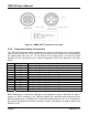
® 2.3 Mounting the TMP100 Attach the TMP100 securely to the vessel using the included stainless steel mounting screws or other fasteners as shown in Figure 1 below. Figure 1 – Mounting the TMP100 2.4 Connecting the TMP100 The TMP100 requires two types of electrical connections: 1) the NMEA 2000® connection (refer to Section 2.4.1), and 2) the temperature probe connections, which are described in Section 2.4.2. 2.4.
TMP100 User's Manual Figure 2 – NMEA 2000® Connector Face Views 2.4.2 Temperature Probe Connections The TMP100 temperature probe connections are made by connecting to the 12-pin terminal strip on the top of the unit. First, remove the four screws at the corners of the unit detaching the splash guard from the unit. On the bottom of the splash guard, you will find a label detailing the wire connection to pin number assignments, which are repeated in the table below.
® 2.4.2.1 Exhaust Gas Temperature (EGT) Probe The TP-EGT-1 exhaust gas temperature probe may be used to measure temperatures other than exhaust gas temperatures; however, the TP-EGT-1 exhaust gas temperature probe is the only TMP100 temperature probe that has sufficient range to measure exhaust gas temperature. NOTE: You may connect TP-EGT-1 exhaust gas temperature probes only to the terminal pairs T0+/T0- (pins 1 and 2) or T1+/T1- (pins 3 and 4).
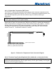
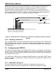
TMP100 User's Manual Please refer to Figure 4 for connecting the TMP100 to a TR3K ring/under bolt thermistor temperature probe, TP-AAP-1 ambient air temperature probe, or TP-IP-1 immersion temperature probe. This figure shows the connection of the TP-IP-1 immersion probe to channel 2 via the terminals named T2+ and T2-, the TR3K ring/under bolt probe to channel 3 via the terminals named T3+ and T3-, and the TP-AAP-1 ambient air probe to channel 4 via the terminals named T4+ and T4-.
® Temperature, Inside Temperature, Engine Room Temperature, Main Cabin Temperature, Live Well Temperature, Bait Well Temperature, Refrigeration Temperature, Heating System Temperature, Freezer Temperature, Exhaust Gas Temperature, and User Defined Temperature #129-#144.. You may also disable the channel by programming the “Disabled” value into this field. 2.5.2 Channel #2 - #5 Source You must configure the TMP100 as to what type of temperature measurement it is transmitting.
TMP100 User's Manual 2.5.5.3 Installation Description… The TMP100, along with all other Level A certified NMEA 2000 devices, has two userprogrammable installation description fields. You may program these fields with information specific to the device, such as date installed, the initials/name of the installer, the physical location of the device, etc. This configuration option will allow you to program the values of these fields.
® 5 Technical Specifications As Maretron is constantly improving its products, all specifications are subject to change without notice. Maretron products are designed to be accurate and reliable; however, they should be used only as aids to navigation and not as a replacement for traditional navigation aids and techniques.
TMP100 User's Manual 128723 Temperature, High Range (Exhaust Gas Temperature) 0.5 times/second Electrical Parameter Operating Voltage Power Consumption Load Equivalence Number (LEN) Reverse Battery Protection Load Dump Protection Value 9 to 32 Volts 50 mA 1 Yes Yes Comment DC Voltage NMEA 2000® Interface NMEA 2000® Spec. (1LEN = 50 mA) Indefinitely Energy Rated per SAE J1113 Mechanical Parameter Value Comment 3.50” x 4.20” x 2.03” Including Flanges for Mounting (88.9mm x 106.7mm x 51.6mm) 13 oz.
® 7 Installation Template Please check the dimensions before using the following diagram as a template for drilling the mounting holes because the printing process may have distorted the dimensions. Figure 5 – Mounting Surface Template Revision 1.
TMP100 User's Manual 8 Maretron (2 Year) Limited Warranty Maretron warrants the TMP100 to be free from defects in materials and workmanship for two (2) years from the date of original purchase. If within the applicable period any such products shall be proved to Maretron’s satisfaction to fail to meet the above limited warranty, such products shall be repaired or replaced at Maretron’s option.
® Appendix A – NMEA 2000® Interfacing TMP100 NMEA 2000® Periodic Data Transmitted PGNs PGN 130310 – Environmental Parameters (not recommended for new designs; included for backward compatibility) The TMP100 uses this PGN to provide a regular transmission of water temperature and outside air temperature. The factory default for periodic transmission rate is twice per second. The transmission of this PGN can be disabled (see PGN 126208 – NMEA Request Group Function – Transmission Periodic Rate).
TMP100 User's Manual PGN 130312 –Temperature The TMP100 uses this PGN to provide a regular transmission of various temperatures. The factory default for periodic transmission rate is once every two seconds. The transmission of this PGN can be disabled (see PGN 126208 – NMEA Request Group Function – Transmission Periodic Rate). Field 1: SID – The sequence identifier field is used to tie related PGNs together.