® ALM100 Alarm Module User’s Manual Revision 1.0 Copyright © 2008 Maretron, LLP All Rights Reserved Maretron, LLP 9014 N. 23rd Ave #10 Phoenix, AZ 85021-7850 http://www.maretron.com Maretron Manual Part #: M001901 Revision 1.
ALM100 User's Manual Revision History Revision 1.0 Original document Page ii Description Revision 1.
® Table of Contents 1 Introduction ...........................................................................................................................1 1.1 Firmware Revision .................................................................................................... 1 1.2 ALM100 Features ..................................................................................................... 1 1.3 ALM100 Accessories ...............................................................................
® 1 Introduction Congratulations on your purchase of the Maretron Alarm Module. Maretron has designed and built your ALM100 to the highest standards for years of dependable and accurate service. Maretron’s Alarm Module generates visual and audible alerts for any monitored condition. The Alarm Module includes an extremely loud 105 dB SPL Piezoelectric sounder, along with a red high-brightness LED to indicate an alarm condition.
ALM100 User's Manual 1.3 ALM100 Accessories Maretron offers the following accessories for the ALM100: • CP-WH-ALM100 ALM100 White Faceplate 1.4 Quick Install Installing the Maretron ALM100 involves the following five steps. Please refer to the individual sections for additional details. 1. 2. 3. 4. 5. Unpack the box (Section 2.1) Choose a mounting location (Section 2.2) Mount the ALM100 (Section 2.3) Connect the ALM100 (Section 2.4) Configure the ALM100 (Section 2.5) 2 Installation 2.
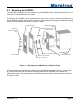
® 2.3 Mounting the ALM100 The ALM100 is designed to be mounted in an ANSI/NEMA WD 6 electrical switch box, but it may also be mounted directly into a wall. If mounting the ALM100 into an electrical box, which can in turn be surface-mounted onto a wall or bulkhead, attach the ALM100 securely to the electrical box using the included mounting screws or other fasteners as shown in Figure 1 below.
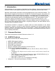
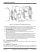
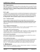
ALM100 User's Manual ALM100 Faceplate Faceplate Mounting Screws (x2) NMEA 2000 Cable (not included) Faceplate Gasket ALM100 Mounting Screws (x2) Sounder Gasket Volume Control Baffle Plate Sounder Collar Volume Control Shutter ALM100 Alarm Module Volume Control Screw Figure 2 – Flush Mounting the ALM100 Directly to a Wall The following instructions apply wither mounting the ALM100 into an electrical box or to a wall: 1) Connect the NMEA 2000 cable to the connector on the ALM100 Alarm Module 2) Using t
® NMEA 2000® network using a Maretron NMEA 2000® cable (or compatible cable) by connecting the female end of the cable to the ALM100 (note the key on the male connector and keyway on the female connector). Be sure the cable is connected securely and that the collar on the cable connector is tightened firmly. Connect the other end of the cable (male) to the NMEA 2000® network in the same manner.
ALM100 User's Manual 2.5.1 Device Instance NMEA 2000® provides a unique device instance for each alarm device on a vessel. This value should be programmed in each ALM100 so that each ALM100 is associated with a unique device instance number. The default instance number is 0, which is used to indicate the first ALM100 that is hooked to the network. Subsequent ALM100s connected to the network would be numbered 1, 2, and so on. 2.5.
® • • • Clean the unit with a soft cloth. Do not use chemical cleaners as they may remove paint or markings or may corrode the ALM100 enclosure or seals. Ensure that the unit is mounted securely and cannot be moved relative to the mounting surface. If the unit is loose, tighten the mounting screws. Check the security of the cable connected to the NMEA 2000® connector, and tighten if necessary.
ALM100 User's Manual 5 Technical Specifications As Maretron is constantly improving its products, all specifications are subject to change without notice. Maretron products are designed to be accurate and reliable; however, they should be used only as aids to navigation and not as a replacement for traditional navigation aids and techniques. Specifications Parameter Annunciator Volume Annunciator Frequency Value 105 dB SPL 2.
® 6 Technical Support If you require technical support for Maretron products, you can reach us in any of the following ways: Telephone: Fax: E-mail: World Wide Web: Mail: Revision 1.0 1-866-550-9100 1-602-861-1777 support@maretron.com http://www.maretron.com Maretron, LLC Attn: Technical Support 9014 N.
ALM100 User's Manual 7 Installation Template Please check the dimensions before using the following diagram as a template for drilling the mounting holes because the printing process may have distorted the dimensions. Figure 4 – Mounting Surface Template Page A10 Appendix A – NMEA 2000 Interfacing Revision 1.
® 8 Maretron (2 Year) Limited Warranty Maretron warrants the ALM100 to be free from defects in materials and workmanship for two (2) years from the date of original purchase. If within the applicable period any such products shall be proved to Maretron’s satisfaction to fail to meet the above limited warranty, such products shall be repaired or replaced at Maretron’s option.