PLAY IT SAFE! OPERATION, MAINTENANCE AND INSTALLATION MANUAL FOR VERTICAL RECYCLER BALER V-4224 CE RATED MODEL VERNON, AL - FAYETTE, AL YERINGTON, NV - CLEARFIELD, PA Marathon Equipment Co. OMI Manual No. 0011CE, Rev.
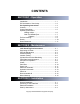
CONTENTS SECTION 1 - Operation Introduction .................................................................. 1-1 EC Declaration of Conformity....................................... 1-2 Pre-Operating Instructions ....................................... 1-3 Controls ....................................................................... 1-4 Control Description ...................................................... 1-5 Operating Instructions Making A Bale ...................................................
1 OPERATION INTRODUCTION THANK YOU FOR PURCHASING A MARATHON VERTICAL BALER. This product is designed to give you reliable service and superior performance for years to come. To guarantee top performance and the safest operation of the baler, each person involved in the operation, maintenance and installation of the baler should read and thoroughly understand the instructions in this manual and follow all warnings.
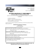
1 OPERATION P.O. Box 1798 Vernon, AL 35592-1798 800-633-8974 205-695-9105 http//www.marathonequipment.
1 OPERATION PRE-OPERATING INSTRUCTIONS STAND CLEAR WHILE BALER IS IN OPERATION. WARNING: DO NOT OPERATE BALER UNTIL OPERATING INSTRUCTIONS ARE THOROUGHLY UNDERSTOOD. NEVER ENTER ANY PART OF THE BALER UNLESS THE DISCONNECT SWITCH HAS BEEN TURNED OFF AND PADLOCKED. Before starting the baler, be sure no one is inside. Be certain that everyone is clear of all points of operation and pinch point areas before starting. See Lock-Out & Tag-Out instructions in the Maintenance section.
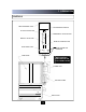
1 OPERATION CONTROLS RED WARNING LIGHT KEYED ON/OFF SWITCH AUTOCYCLE BUTTON EMERGENCY STOP BUTTON MANUAL UP BUTTON MANUAL DOWN BUTTON BALE MADE LIGHT RESET INTERLOCK OVERRIDE FEED GATE *SEE CONTROL DESCRIPTION ON FOLLOWING PAGE POWER UNIT CONTROL PANEL BALE DOOR 1-4
1 OPERATION CONTROL DESCRIPTION 1. ON-OFF (Keyed Selector Switch) Turning this switch to the ON position activates the other controls in the control panel. The baler can not be operated unless the key is in the switch and the switch is in the ON position. The purpose of this switch is to allow only authorized and trained personnel to operate the baler. The key should be removed from the baler when not in use and should stay in the possession of only responsible and trained personnel. 2.
1 OPERATION OPERATING INSTRUCTIONS - MAKING A BALE WARNING: DO NOT OPERATE BALER UNTIL OPERATING INSTRUCTIONS ARE UNDERSTOOD. See page 1-4 for control panel layout. IN CASE OF EMERGENCY: Push the large red button to STOP WARNING: Interlocks and safety devices were installed on this unit for your protection. Never disable or bypass any interlock or safety device. Failure to comply with this warning could result in serious injury or death. TO MAKE A BALE : 1. Feed material into baler.
1 OPERATION OPERATING INSTRUCTIONS - BALE TIE OFF/BALE EJECT When the “BALE MADE” light comes on it is time to tie off the bale and eject the bale from the baler. See page 1-4 for control panel layout and location. See the following page for a diagram of the following steps. FOR BALE TIE OFF & BALE EJECT: 1. Press the MANUAL UP button until the platen is in the up position and the feed gate raises. 2. Insert a large, flat piece of material across the top of the bale.
1 OPERATION DIAGRAM - BALE TIE OFF/BALE EJECT FRONT VIEW OF BALER FEED GATE OPENS WHEN BALE DOOR IS OPENED SIDE VIEW PLATEN BALE TIE SLOTS BALE TIES ENTER THROUGH PLATEN LOOPED END FIRST BALE TIE SLOTS BALE CHAMBER DOOR OPENED BALE TIES FOLLOW WIRE GUIDES BALE TIES EXIT THROUGH FLOOR BALE TIE - TIGHTENED HAND TIGHT BALE DURING EJECTION EJECTED BALE SIDE VIEW - BALE PALLET OR BALE CART RECOMMENDED FOR SUPPORTING BALE 1-8
1 OPERATION TIE SLOT CLEANING AT TIMES THE TIE SLOTS MAY BECOME OBSTRUCTED WITH MATERIAL AND PREVENT THE WIRE TIES FROM PROPER INSERTION THROUGH THE SLOTS AND AROUND THE BALE. THE BALER IS SUPPLIED WITH A SLOT CLEANING TOOL FOR RODDING OUT THE TIE SLOTS. TO USE, INSERT THE TOOL INTO THE BLOCKED SLOT AND PUNCH OR DRAG THE MATERIAL OUT.
1 OPERATION DECALS WARNING DECAL REQUIREMENTS When your baler leaves the factory, several WARNING DECALS are installed for protection. These labels are subject to wear and abuse due to the nature of the operation. THESE DECALS MUST BE MAINTA I N E D. Additional decals may be purchased through your distributor.
1 OPERATION DECAL PLACEMENT 1-11
2 MAINTENANCE LOCK-OUT & TAG-OUT INSTRUCTIONS OFF (Typical disconnect shown, other types may lock-out differently.) FOREWORD: Before entering any part of the baler, be sure that all sources of energy have been shut off, all potential hazards have been eliminated, and the baler is locked-out and tagged-out in accordance with OSHA and ANSI requirements. Before servicing the hydraulic system or the inside of the bale chamber, THE PLATEN MUST BE PROPERLY SUPPORTED AS SHOWN ON THE NEXT PA G E.
2 MAINTENANCE SUPPORTING OF PLATEN WARNING: BEFORE ENTERING BALE CHAMBER FOR SERVICE, BE SURE THAT THE PLATEN IS SECURELY SUPPORTED. AT A MINIMUM, USE TWO WOODEN 100mm x 100mm BEAMS (GOOD CONDITION), CUT TO FIT SNUG IN EACH REAR CORNER OF THE CHAMBER WHILE SUPPORTING THE PLATEN IN THE UP POSITION. THE TOP END OF EACH BEAM SHOULD BE IN THE EXTREME CORNER, WHILE THE BOTTOM END SHOULD BE POSITIONED OVER THE OUTER TIE SLOT IN THE FLOOR. SEE DIAGRAM BELOW. DANGER: DO NOT CLIMB ON SIDES OF BALER.
2 MAINTENANCE PERIODIC MAINTENANCE WARNING: BEFORE PERFORMING ANY MAINTENANCE OR SERVICE PROCEDURES ON THE BALER, MAKE SURE THE BALER IS LOCKED-OUT AND TAGGED-OUT PER THE INSTRUCTIONS ON PAGE 2-1. FOR MAINTENANCE INSIDE THE BALE CHAMBER, SEE THE PLATEN CHOCKING PROCEDURE ON PAGE 2-2. MONTHLY 1. Check external hoses for chafing, rubbing, leakage, or other deterioration and damage. Tighten all fittings as necessary. Check hydraulic cylinder, cylinder pin and bolts for signs of wear and fatigue. 2.
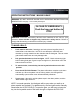
2 MAINTENANCE PRESSURE SETTING DANGER: DO NOT CLIMB ON SIDES OF BALER. USE A LADDER OR WORK PLATFORM WHEN WORKING ON TOP OF THE BALER OR OTHER AREAS OF THE BALER THAT CAN NOT BE REACHED FROM GROUND LEVEL. WARNING: FEED GATE WILL EXTEND ABOVE THE TOP OF THE BALER WHEN THE FEED GATE IS RAISED. HYDRAULIC SYSTEM PRESSURE SETTING 1. Using the “MANUAL DOWN” button, run the platen to the fully down position. RELIEF VALVE 2. Lock-out and Tag-out the power per the “A” PORT instructions on page 2-1. 3.
2 MAINTENANCE PRESSURE SETTING AND INTERLOCK TESTING DANGER: DO NOT CLIMB ON SIDES OF BALER. USE A LADDER OR WORK PLATFORM WHEN WORKING ON TOP OF THE BALER OR OTHER AREAS OF THE BALER THAT CAN NOT BE REACHED FROM GROUND LEVEL. WARNING: FEED GATE WILL EXTEND ABOVE THE TO P OF THE BALER WHEN THE FEED GATE IS RAISED. HYDRAULIC SYSTEM PRESSURE SETTING-(continued) 14. Continue to press the “MANUAL DOWN” button and adjust the Relief Valve to 1800 psi. 15. While holding 1800 psi.
2 MAINTENANCE CYLINDER REMOVAL AND REBUILDING DANGER: DO NOT CLIMB ON SIDES OF BALER. USE A LADDER OR WORK PLATFORM WHEN WORKING ON TOP OF THE BALER OR OTHER AREAS OF THE BALER THAT CAN NOT BE REACHED FROM GROUND LEVEL. WARNING: FEED GATE WILL EXTEND ABOVE THE TOP OF THE BALER WHEN THE FEED GATE IS RAISED. CYLINDER REMOVAL 1. 2. 3. 4. 5. 6. 7. 8. 9. 10. 11. 12. 13. 14. 15. 16. 17. Close the feed gate. Turn on power and lower the platen using the MANUAL DOWN button. Turn off power.
2 MAINTENANCE FEED GATE LATCH ADJUSTMENT NOTE: Adjustment is made by tightening or loosening the TENSION ADJUSTMENT NUT with the feed gate in the up position. Spring tension should not exceed 5 lbs to prevent excessive wear on the feed gate latch and striker. TENSION ADJUSTMENT NUT FEED GATE SPRING STRIKER FEED GATE LATCH BALE DOOR BOLTS FOR STRIKER NOTE: In the event of excessive wear, the feed gate latch STRIKER is removable and replaceable.
2 MAINTENANCE PRINCIPLES OF OPERATION OPERATING CHARACTERISTICS: With the key switch in the ON position, and the bale door and feed gate closed, pressing the AUTOCYCLE push button will cause the machine to operate one complete cycle. Pressing the AUTOCYCLE switch closes three sets of contacts: (1) energizes Relay 1, (2) energizes Relay 2, (3) energizes the motor starter coil. With the motor running, oil is supplied to the subplate and directional control valve.
2 MAINTENANCE CHARTS ELECTRICAL REQUIREMENTS 5 HP 400V 3 PHASE 50HZ VOLTAGE 208 VAC 230 VAC 400 VAC/50 HZ FULL LOAD AMPERAGE 16.7 15.2 8.
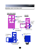
2 MAINTENANCE PANEL BOX GROUND TIMER TERMINAL BLOCK OVERLOAD ADJUSTMENT MOTOR STARTER W/OVERLOADS GROUND RELAYS AND BASES TERMINAL STRIP 2-10 2 AMP FUSE
2 MAINTENANCE POWER UNIT DIRECTIONAL CONTROL VALVE COUNTERBALANCE VALVE RELIEF VALVE (RV1) PUMP SUBPLATE PUMP/MOTOR ADAPTER CLEAN OUT COVER HUB COUPLING BREATHER CAP MOTOR SUCTION FILTER (LOCATED IN RESERVOIR) SIGHT GAUGE NOTE: See RECOMMENDED OIL on page 2-14.
2 MAINTENANCE ELECTRICAL SCHEMATIC E-6415 2-12
2 MAINTENANCE HYDRAULIC SCHEMATIC E-0489 5 HP / 3.7 KW 6 GPM / 22.
2 MAINTENANCE PARTS LIST PART # 02-0050 02-0197 02-0198 02-0219 02-0628 02-3902 02-4037 02-4207 02-0242 99-7778 02-4018 03-0010 03-0012 03-4152 03-4730 03-4729 03-5013 03-0335 03-0351 DESCRIPTION PART # SUCTION FILTER BREATHER SIGHT GAUGE CLEAN OUT COVER DIRECTIONAL CONTROL VALVE COUNTER BALANCE VALVE PUMP/MOTOR ADAPTER SUBPLATE HUB COUPLING PUMP RELIEF VALVE LIMIT SWITCH ARM LIMIT SWITCH RELAY SAFETY MONITORING PLC EXPANSION 4 IN 2 OUT PLC 6 IN 4 OUT MOTOR STARTER OVERLOAD RED OMNIGLOW LIGHT TIMER RETAI
3 INSTALLATION GENERAL INSTALLATION CAUTION: Review this manual before beginning the installation. Study the jobsite and installation requirements carefully to be certain all necessary safeguards and/or safety devices are provided to protect all personnel and equipment during the installation and as a completed system. These instructions are not intended as a substitute for training and experience in proper use, safety procedures, maintenance, or installation of this equipment.
3 INSTALLATION ANCHORING TO CONCRETE PAD The concrete pad should be level, and a minimum of 3000 PSI concrete, steel reinforced, 150mm thick. Anchor baler to floor using anchor brackets on sides of baler base. Two 18mm diameter anchor bolts required, Red Head type recommended. 1. Roll baler to the desired location. 2. Unbolt the Anchor Bracket from the baler. (both sides) ANCHOR BRACKET IN SHIPPING POSITION 3. Turn the Anchor Brackets over and re-bolt them to the baler. 4.
3 INSTALLATION ELECTRICAL INSTALLATION DANGER 400 460 VOLTS 06-0045 The panel box contains high voltage components. Only authorized service personnel should be allowed inside. See Lock-Out & Tag-Out instructions in the Maintenance section. WARNING: BEFORE MAKING ANY ELECTRICAL CONNECTION, BE SURE THAT THE MAIN DISCONNECT SWITCH HAS BEEN LOCKED-OUT AND TAGGEDOUT PER THE LOCK-OUT AND TAG-OUT INSTRUCTIONS ON PAGE 2-1. 1.
3 INSTALLATION START-UP INSTRUCTIONS WARNING: BEFORE START-UP, REPLACE THE 3/4” PLUG ON THE TOP OF THE POWER UNIT R E S E RVOIR WITH THE FILLER BREATHER CAP. THIS CAP I S SHIPPED INSIDE OF THE PANEL BOX. DANGER: DO NOT CLIMB ON SIDES OF BALER. USE A LADDER OR WORK PLATFORM WHEN WORKING ON TOP OF THE BALER OR OTHER AREAS OF THE BALER THAT CAN NOT BE REACHED FROM GROUND LEVEL. WARNING: PARTS OF THE FEED GATE WILL EXTEND ABOVE THE TOP OF THE BALER WHEN THE FEED GATE IS FULLY RAISED.