UNIPRO v3.
Marathon Monitors Inc. Description and Applications The Marathon Monitors Inc. UNIPRO Controller/Programmer represents the latest technology in microprocessor-based process control instrumentation. Through flexible PID (Proportional, Integral, Digital) control along with programmable features, even the most complex, system can be handled. For a thorough explanation of PID please refer to Zeigler and Nichols; “Optimum Settings for Automatic Controllers”, Transactions of ASME, Nov. 1942. Or St.
Marathon Monitors Inc. Two (2) control output triacs for use in single or dual control mode. Two (2) fully isolated analog outputs, each separately configurable for voltage or current output. Two (2) configurable alarm triacs, assignable as process Alarms, deviation alarms, program alarms, or fault alarms. Four (4) programmer events, assignable in any combination as either inputs or outputs (expandable to 16 I/O with external event boards).
Marathon Monitors Inc. Installation Installation Location The UNIPRO instrument is designed for 1/8 inch panel mounting in a DIN standard opening of 5.43 inches square (adapter panels available by special order). Required rear clearance is 10.5 inches to allow for wiring. As with all solid state equipment, the controller should be away from excessive heat, humidity, and vibration (refer to specifications).
Marathon Monitors Inc. Unipro 3.5 Process Control 1 Aug.
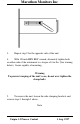
Marathon Monitors Inc. 3. Repeat step 2 for the opposite side of the unit. 4. With 1/8 inch HEX KEY wrench, alternately tighten bolts on either side of the instrument to a torque of 4 in-lbs. (See warning below). Insure rigidity of mounting. Warning To prevent warping of the unit's case, do not over tighten the clamp bolts. 5. To remove the unit, loosen the side clamping brackets and reverse steps 1 through 3 above. Note Unipro 3.5 Process Control 1 Aug.
Marathon Monitors Inc. On subsequent removals and installations the rear panel can be removed (4 screws) and the wiring does not have to be disturbed. Warning All connections, rear panel installations and removals; plus triac board installations and removals must be done with power removed from TBA and TBB. All PC boards should only be removed or installed with power off via the switch mounted on the triac board. Otherwise, serious personal and/or equipment damage can occur.
Marathon Monitors Inc. Three types of Proportional control are: 1. Time-Proportioning: Referring to the modulation of the duty cycle. That is, changing the ratio of On Time versus Off Time in systems that use such devices as heating elements, electronically operated/assisted valves, or servo drives that use analog command signals for control. 2. Position-Proportioning: Referring to the adjustment of a variable positioning device such as a positioning motor with slidewire feedback. 3.
Marathon Monitors Inc. more details). The output control is based on 0 to 99% of the output device's control range. For example, 50% control would equal 2.5 VDC out where 5 VDC equals maximum heat output of the drive. This can be used with servo drives that require a voltage or current command signal for controlling heat output or servo positioning. 3. POSITIONING MOTOR with SLIDEWIRE FEEDBACK: Set Control Modes for Single Position-Proportioning with slidewire feedback.
Marathon Monitors Inc. Alarms Two user-programmable triac alarm contacts are available for connection in appropriately-engineered systems. Programmer The Programmer can run an entire process, depending on how thoroughly the capabilities are set up and used. Refer to "Operation" and "Programming" for further information. Unipro 3.5 Process Control 1 Aug.
Marathon Monitors Inc. Electrical Connections Connections to the unit are made via four terminal blocks, on the rear panel, labeled TBA, TBB, TBC, and TBD. (Position 1 is at the top the position 10 (TBA and TBB) or 18 (TBC and TBD) is at the bottom of the terminal strip.) AC power, event, control, and alarm connections are made on TBA and TBB. All communications are on TBC and all analog I/O signals are on TBD. Refer to the Figure below for a complete layout of the UNIPRO rear panel connections. Unipro 3.
Marathon Monitors Inc. Unipro 3.5 Process Control 1 Aug.
Marathon Monitors Inc. UNIPRO Rear Panel UNIPRO Electrical connections AC Power The UNIPRO requires 100/120/200/240 VAC at 1 AMP, Communications Three communications busses are at TBC and use RS-422 full or half duplex protocol for all ports. (Refer to "Communications" in Maintenance and Troubleshooting.) Typically, the HOST port will connect to a host computer, the AUXILIARY BUSS to other instruments, and the OPTOMUX PORT to OPTOMUX I/O devices. Unipro 3.5 Process Control 1 Aug.
Marathon Monitors Inc. Analog Inputs The UNIPRO allows for three analog inputs with their individual functions determined by "daughter board" located on the analog input board inside the unit. The standard connection, at TBD, will have the first input as a thermocouple, the second for the oxygen probe, and the third optionally used to input voltage or milliamp signals.
Marathon Monitors Inc. UNIPRO Front Panel Removal Find the appropriate switches by referring to the figure below. Unipro 3.5 Process Control 1 Aug.
Marathon Monitors Inc. UNIPRO Internal Layout DIP Switch Assignments Bank 0 Switch # Description 1 Unassigned 2 Unassigned 3 Slide wire Deadband (see the following table) 4 Slide wire Deadband (see the following table) 5 Slide wire Deadband (see the following table) 6 Unassigned 7 Unassigned 8 Service (Must be OFF) Selectable deadband for slidewire feedback control. Unipro 3.5 Process Control 1 Aug.
Marathon Monitors Inc. Slidewire Dead Band Offset offset Switch 3 0.4% OFF Switch 4 OFF Switch 5 OFF 0.8% ON OFF OFF 1.2% OFF ON OFF 1.6% ON ON OFF 2.0% OFF OFF ON 2.4% ON OFF ON 2.8% OFF ON ON 3.2% ON ON ON Unipro 3.5 Process Control 1 Aug.
Marathon Monitors Inc. Each UNIPRO in a multiple instrument system must have a unique address for proper communications.
Marathon Monitors Inc. Thermocouple Burnout Jumper Selection The thermocouple jumper selects either a full upscale or a full down scale reaction to take place when a thermocouple fails or becomes open. The jumper can be found on the thermocouple board, and has two possible settings (see Figure). For full scale upwards, place the jumper from the + to the C, and for full scale downwards, place the jumper from the - to the C. Unipro 3.5 Process Control 1 Aug.
Marathon Monitors Inc. Setup And Configuration Front Panel The front panel of the UNIPRO consists of three main parts, two display windows and a keyboard. Refer to the figure shown below for a layout of the front panel. The display windows each contain four 14-segment digits that are used to display helpful messages and numerical parameter values.
Marathon Monitors Inc. This 4 digit 14-segment display provides the value of the process setpoint value during Auto and Program operation. In Manual mode the Time-Proportioning % Output value is displayed. During operator input procedures this display shows the data being entered. The SET window displays the corresponding data for the OPCODES displayed in the PROCESS window when in the Program Editor. LEDs Several small LEDs indicate operations and functions of the UNIPRO.
Marathon Monitors Inc. Fault indicates that an open circuit is detected at the signal input. Wait indicates that the Programmer is waiting for some condition to be satisfied before continuing. Setpt indicates that the Setpt Enter mode has been selected. Cntrl Parm indicates that the Control Parameter Enter mode has been selected. Alarm Set indicates that the Alarm Setup mode has been selected or one or both alarm values are non-zero. Unipro 3.5 Process Control 1 Aug.
Marathon Monitors Inc. Keyboard The UNIPRO keyboard consists of ten keys for operating and programming the instrument. There are no "hidden" keys on the UNIPRO keyboard. Various operations with the UNIPRO involve dual-key operations using the [Shift] key in the same way a shift key on a typewriter is used. When activating a dual-key assignment do not try to press both keys simultaneously; rather, follow the sequence below: 1. 2. 3.
Marathon Monitors Inc. This key selects the Control Parameter Enter mode where the Proportional Band, Reset, Rate, Cycle Time and Percent Output values (if in solenoid mode) can be accessed and altered. When used in the dual-key operation Shift/Cntrl Parm it selects the keyboard Lock Level change mode. This key selects the Alarm Setup mode where the Alarm 1 and Alarm 2 conditions can be accessed and altered or Alarm 2 can be used to determine setpoint for auxiliary control loop.
Marathon Monitors Inc. usually used to select which digit is to be modified in a data entry mode. In Manual mode this key will cause the control output to go to the full reverse control direction while the value is displayed in the SET window. In Automatic mode pressing "left arrow" causes the % on-time valve position to be displayed in the SET window. (positive-Output 1, negative-Output 2). In the Programmer Status Display it causes the display to move to a new page.
Marathon Monitors Inc. usually used to select which digit is to be modified in a data entry mode. In Manual mode this key will cause the control output to go to the full Output 1 direction. In the Programmer Status Display mode it causes the display to move to a new page. this key is used to enter data, clear alarms, or cancel programs. Unipro 3.5 Process Control 1 Aug.
Setup and Configuration Unipro 3.5 [ C o n t r o l P a r a m e t e r ] S e t u p M e Unipro 3.5 Process Control 1 Aug.
Setup and Configuration Unipro 3.5 n u ME PR a x MENU CON pb xxxx MENU INP in a xxxx MENU AOUT ao 1 xxxx MENU COM host xxxx res xxxx cjca xxxx ao1o xxxx auxm xxxx x rate xxxx iaof xxxx ao1r xxxx aux xxxx a x cyc xxxx iasp xxxx ao2 xxxx ssoa xxx lo p hipo xxxx iadp xxxx ao2o xxxx sso1 xxxx lo lopo xxxx in b * ao2r xxxx : : ldln xxxx in conv xxxx C * sso8 xxxx Tc ºX Cm x xx setp xxxx n o t e s : * f u l l s e Unipro 3.5 Process Control 1 Aug.
MMI Product Documentation q u e n c e o f “ I N A ” r e p e a t s f o r i n p u t s B Unipro 3.5 Process Control 1 Aug.
Setup and Configuration Unipro 3.5 a n d C . : t h e s c r e e n r e p e a t s f o r n u Unipro 3.5 Process Control 1 Aug.
MMI Product Documentation m b e r s 0 8 d e c i m a l a n d h e x a n d h e x n Unipro 3.5 Process Control 1 Aug.
Setup and Configuration Unipro 3.5 u m b e r s 9 f . T h i s i n d i c a t e s t h a t t h e Unipro 3.5 Process Control 1 Aug.
MMI Product Documentation r e p e a t i n g s c r e e n s h a v e b e e n l e f t o u t Unipro 3.5 Process Control 1 Aug.
Setup and Configuration Unipro 3.5 b e t w e e n t h e f i r s t a n d l a s t n u m b e r s . Unipro 3.5 Process Control 1 Aug.
MMI Product Documentation Control Parameter Key Menu Selections The following shows the order of configuration options set from the [Cntl Parm] key and their range of values. Press [ENTER] to go forward to the next option, or [Shift] to back up to a previous option. The arrow keys are used to change the option within its limits see the keys portion of this section for a complete description of how they are used. Pressing [Cntl Parm] at any time will exit from this option setup sequence.
Setup and Configuration Unipro 3.5 e t d i s p l a y o p t i o n s D e s c r i p t i o n 0 to 9999 Propor Unipro 3.5 Process Control 1 Aug.
MMI Product Documentation tional band 0 to 99.99 Reset 0 to 9.99 Rate 1 to 250 Cycle time in second s 0 to 100 High limit Unipro 3.5 Process Control 1 Aug.
Setup and Configuration Unipro 3.5 on percent output -100 to 100 Low limit on percent output -100 to 100 Load Line Unipro 3.5 Process Control 1 Aug.
MMI Product Documentation CON menu Continued... Process display Set display Descri ption xxx Contro l mode XXX= X__ = D or R for direct or reverse . Unipro 3.5 Process Control 1 Aug.
Setup and Configuration Unipro 3.5 _XX = tp for time propor tioning . tc for time propor tioning with compli ment td for time propor tioning dual Unipro 3.5 Process Control 1 Aug.
MMI Product Documentation ms for motor with slide wire feedba ck of for OFF / ON control oc for OFF / ON with compli ment Unipro 3.5 Process Control 1 Aug.
Setup and Configuration Unipro 3.5 od for OFF / ON dual pp for positio n propor tioning LOC , IN C Setpoi nt source; local or input C Unipro 3.5 Process Control 1 Aug.
Setup and Configuration Unipro 3.5 INP menu Input A, B, or C values and actions are programmed from this menu. Display choices shown are for input A. The other input choices follow through the same cycle. Exceptions are noted in the table. Thermocouple degree choices for temperature display come at the end of the full menu cycle. Proces s d i s p l a y S e t d i s p l a y c Unipro 3.5 Process Control 1 Aug.
MMI Product Documentation h o i c e s D e s c r i p t i o n L I N , T c , O f f , Unipro 3.5 Process Control 1 Aug.
Setup and Configuration Unipro 3.5 P r o g L i n e a r i z a t i o n f o r i n p u t A : Unipro 3.5 Process Control 1 Aug.
MMI Product Documentation L I N f o r l i n e a r T c ? F o r t h e Unipro 3.5 Process Control 1 Aug.
Setup and Configuration Unipro 3.5 r m o c o u p l e t y p e * O f f P Unipro 3.5 Process Control 1 Aug.
MMI Product Documentation r o g f o r P r o g r a m m e d . I n p u t C h a s t h r e e Unipro 3.5 Process Control 1 Aug.
Setup and Configuration Unipro 3.5 m o r e c h o i c e s L 3 0 , L 5 0 , a n d L 1 0 0 . Unipro 3.5 Process Control 1 Aug.
MMI Product Documentation Y E S, NO Cold junctio n compe nsation active for input A -999 to 9999 Input A offset for progra m mode -999 to 999 Input A span value for progra Unipro 3.5 Process Control 1 Aug.
Setup and Configuration Unipro 3.5 m mode 0 to 3 Input A display ed decima l point locatio n for progra m mode. de g F, deg C Tempe rature display units Notes: * thermocouple types are found in the specifications. Values and types are also found in Maintenance and Troubleshooting. Unipro 3.5 Process Control 1 Aug.
MMI Product Documentation AOUT menu P Unipro 3.5 Process Control 1 Aug.
Setup and Configuration Unipro 3.5 P O , I N B , P 2 0 , P 2 Unipro 3.5 Process Control 1 Aug.
MMI Product Documentation 1 , A n a l o g o u t p u t 1 s o u r c e * REFN, PROG, TEMP, AUX 9 Unipro 3.5 Process Control 1 Aug.
Setup and Configuration Unipro 3.5 9 9 t o 9 9 9 9 A n a l o g o u t p u t 1 o f f s e t Unipro 3.5 Process Control 1 Aug.
MMI Product Documentation 0 t o 9 9 9 9 A n a l o g o u t p u t 1 r a n g e Unipro 3.5 Process Control 1 Aug.
Setup and Configuration Unipro 3.5 Analog out put 2 choices are the same menu items repeated. *Analog output source 1 menu items: PO = percent output IN B = input B P 20 & P 21 are specialized parameter settings. Check with your programmer before entering data. REFN = the reference number PROG = the program TEMP = temperature AUX =Auxiliary output Unipro 3.5 Process Control 1 Aug.
MMI Product Documentation COM menu P r o c e s s d i s p l a y S e t d i s p l a y D e s c r i p Unipro 3.5 Process Control 1 Aug.
Setup and Configuration Unipro 3.5 t i o n H or F, E or N Host commu nicatio ns setup and 0 to 3 TE M or UDC Aux commu nicatio ns port mode; MMI 10Pro or Honey well UDC3 000 Unipro 3.5 Process Control 1 Aug.
MMI Product Documentation H or F, E or N Aux commu nicatio ns setup and 0 t o 3 NO, YES Slave setpoin t offset active -500 to 500 Slave temper ature Unipro 3.5 Process Control 1 Aug.
Setup and Configuration Unipro 3.5 control ler setpoin t offset The UNIPR O can transfe r7 slave temper atures and have an offset for each. Addres s 1 is the original UNIPR O. Notes: communications choices for the UNIPRO are: H = Half or F = full duplex E = even or N = no parity BAUD rate code 0 = 1200 1 = 4800 Unipro 3.5 Process Control 1 Aug.
MMI Product Documentation 2 = 9600 3 = 19.2k Unipro 3.5 Process Control 1 Aug.
Setup and Configuration Unipro 3.5 PROG menu P r o c e s s d i s p l a y S e t d i s p l a y D e s c r i Unipro 3.5 Process Control 1 Aug.
MMI Product Documentation p t i o n NO, YES Auto startup NO, YES Auto progra m start NO, YES Asynch ronous event 0 to 3 Unipro 3.5 Process Control 1 Aug.
Setup and Configuration Unipro 3.5 Lock level The most accessi ble level is 3, the least is 0. To set a passwo rd see below. Password Entry The password can be entered by pressing the Dual-key sequence [Shift] + [Cntl. Parm] keys. Any order of keys, except for the [Shift] or [ENTER] key, can be entered as a password, up to nine keys maximum. Press [ENTER] to save the password. The number in the set display will count the number of keys entered. Pressing [ENTER] without pressing any other key (i.e.
MMI Product Documentation [Cntl Parm], [Enter], [Enter] ,[Enter] must be pressed. Unipro 3.5 Process Control 1 Aug.
Setup and Configuration Unipro 3.5 EVTS menu P r o c e s s d i s p l a y S e t d i s p l a y o p t i o n s Unipro 3.5 Process Control 1 Aug.
MMI Product Documentation D e s c r i p t i o n NO, YES Extern al event boards active 1200 , 4800 Events commu nicatio ns baud rate Unipro 3.5 Process Control 1 Aug.
Setup and Configuration Unipro 3.5 0 to 4 Eve nts partitio n internal 0 to 16 Extern al analog board partitio n? Where ? is 0,1, 2, 3, 4, 5, 6, 7, 8, 9, A, B, C, D, E, F Repres enting module s0 Unipro 3.5 Process Control 1 Aug.
MMI Product Documentation throug h 15 respect ively. XXX Extern al analog board module lineariz ation. Where XXX = lin, prog, n/a or thermo couple type and value * Unipro 3.5 Process Control 1 Aug.
Setup and Configuration Unipro 3.5 All thermocouple displays have TC X format where X = thermocouple type. See the list below Thermocouple list: Display T/c Type B C E J K N NM R S T Unipro 3.5 Process Control 1 Aug.
MMI Product Documentation [Alarm Set] key The [Alarm Set] key also sets some parameters. Its menu is limited to alarm functions. Again [Enter] and [Shift] move forward or back through the selections while setting up, [arrow] keys change values and [Alarm Set] exits. All values are saved as they are changed. Alarm Set key P r o c e s s d i s p l a y S e t d i s p l Unipro 3.5 Process Control 1 Aug.
Setup and Configuration Unipro 3.5 a y o p t i o n s D e s c r i p t i o n See not es Alarm 1 mode. Selects which variabl e, type Rev. 8.
MMI Product Documentation of alarm, and whethe r direct or reverse acting. See notes below. -999 to 9999 Alarm 1 value. Decim al point is automa tically set based on control variabl e and type of alarm. 0 to 250 Unipro 3.5 Process Control 1 Aug.
Setup and Configuration Unipro 3.5 Alarm 1 turn on delay time in second s. 0 to 250 Alarm 1 turn off delay time in second s. At this point, if there is no need for ALARM 2 to be set, press [Alarm Set] to exit alarm parameters. If ALARM 2 does need to be set, press [Enter]. Use the information starting at the top of the table for ALARM 1. The process display will change only from a 1 to a 2. All other information in the table remains accurate for ALARM 2. Notes: Variable Rev. 8.
MMI Product Documentation D This is DIRECT operation for alarm actuation (i.e. the contact is normally open until it reaches the trigger limit specified in the ALARM VALUE then the contact closes). Notes: continued Variable Description R REVERSE operation (opposite of NORMAL) for ALARM actuation (i.e. the alarm contact is normally closed until it reaches the trigger limit specified in the ALARM VALUE then the contact opens).
Setup and Configuration Unipro 3.5 programmed setpoint is at 0.80, the alarm will trigger at 0.90 and 0.70.) DEV Alarm actuation uses DEVIATION control above or below the programmed setpoint. The + and - symbols determine if the deviation is allowed or if it is above (+) the programmed setpoint or below (-) it. (i.e. If deviation of 0.10 is placed in the ALARM VALUE and 0.80 is the programmed SETPOINT the alarm will trigger at 0.90 or 0.70, for -0.10.
MMI Product Documentation [SETPT] key Parameter entry under the [Setpt] key is the same procedure as under the other two keys controlling parameters. [Enter] moves forward [Shift] moves back and [arrow] keys change the values in a parameter. [Setpt] exits and values are saved when changed. Setpt key P r o c e s s d i s p l a y S e t d i s p l Unipro 3.5 Process Control 1 Aug.
Setup and Configuration Unipro 3.5 a y o p t i o n s D e s c r i p t i o n -999 to 9999 Contr ol loop setpoi nt. The locatio n of Rev. 8.
MMI Product Documentation the setpoi nt will be autom aticall y set based on the contro l loop proces s variab le. 0 to 9999 Refere nce numbe r. -999 to 9999 Opera tor input which can be Unipro 3.5 Process Control 1 Aug.
Setup and Configuration Unipro 3.5 access ed by the host compu ter system . Rev. 8.
MMI Product Documentation Unipro 3.5 Process Control 1 Aug.
Operation UNIPRO 3.5 OPERATION Once installation and setup and configuration are complete, the day to day operation needs of the UNIPRO depend upon the application. The basics are found in the Quick Reference Guide. TO RESPOND TO ALARM MESSAGES: Note the alarm and determine what caused the alarm. Press [ENTER] once to deactivate (silence) alarm relay contact and continue program execution.
MMI Product Documentation Correct the problem or do what the programmed alarm indicates: see “Maintenance and Troubleshooting”: the alarm messages for complete information on programmed alarms. Then press [Enter] to continue the program. If any alarm is only to be acknowledged and the operation is to continue, press [ENTER] to silence the alarm and then press [SETPT] to skip to the next operation.
Operation UNIPRO 3.5 SETPOINT PARAMETERS Display Parameters Stpt Description Setpoint The SET display window line represents the basic parameter for the Control Loop that the process needs. REF Reference Number Assign s a number to a program for future reference. These numbers can range from 0 to 9999. NM Rev. 11.00 December 30,1995 Operator Input SET display window line = -999 to 9999. Allows the operator to enter information that may be needed by a program.
MMI Product Documentation PROG/AUTO/MAN The Operation Mode for control of programs is selected by the [Prog/Auto/Man] key. Pressing this key allows access to the operation mode selection controls. The first selection, after pressing [Prog/Auto/Man], allows for control of the program to be entered. The key presses that follow it depend upon the state of the program. If a program is not running see “Running A Program” below.
Operation UNIPRO 3.5 Either the percent ON time (time-proportion) or valve position (position proportion) is displayed in the SET window. For single control mode operation this number is always positive (0/50/100). The [UP ARROW] and the [DOWN ARROW] keys increase or decrease the percent ON time or the valve position toward its fully opened or closed positions by approximately 1%. This continues for as long as the key is pressed.
MMI Product Documentation PROGRAM OPERATIONS Running a Program Press [PROG/AUTO/MAN] until the instrument's Prog LED lights. 2. The Program Number is displayed in the SET display, select the program to be run using the arrow keys. OPTIONAL: If beginning at a step other than 1 Repeatedly press the [SHIFT] key to select the step upon which the program should start. The step number will appear in the PROCESS display. 4. Press [ENTER] to run the program. 5.
Operation UNIPRO 3.5 Press the [PROG/AUTO/ MAN] key until the Auto or Man LED is flashing, indicating a program is in HOLD. Return to the program mode by pressing [PROG/AUTO/MAN] and the PROCESS window will display the word HOLd. The SET window indicates the program number that is in hold. Press any of the arrow keys to cancel the program. The hold symbol will be replaced by the run symbol. 1.
MMI Product Documentation 1. 2. 3. Restarting a Program From HOLD Press [PROG/AUTO/MAN] UNTIL the instrument is in Programmer mode as indicated by the Prog LED. The LED should be flashing signifying a program is in HOLD. OR Press [SHIFT] +[LEFT ARROW]. Do not alter the program number, otherwise, the program will start from the first step and not where it had left off. Press [ENTER] and the program will continue executing with the step where the HOLD was initiated. To Enter Program Editor* 2. 1.
Operation UNIPRO 3.5 the data in the SET display is invalid for the OPCODE shown. Use the [arrow keys] to enter the correct data and then press [ENTER]. To Insert A Step 1. Go to the step of the desired insertion, using either the [ENTER] or [Shift] keys 2. Press [Control Parm] 3. Enter the new step, OPCODE and data 4. Press [ENTER] To Delete A Step 1. Go to the step to be deleted, using either[ Enter] or [Shift] 2. Press [Alarm Set] Rev. 11.
MMI Product Documentation To Exit the Editor Without Saving the Program 1. Press [Setpt ]at any time, the edited program is lost (the copy in non-volatile memory is unchanged) To Exit the Editor Saving the Program 1. Edit through step 19 as required, inserting NOP's wherever no operation is to be executed 2. Press [ENTER] 3. Select the program number in the SET display using the [arrow keys] until the desired program number is being displayed (SAVE / 0000) 4.
Operation UNIPRO 3.5 After all characters are as wanted, press the [ALARM SET] key to place the value in memory and exit, or press [ENTER] to save the value and continue (forward) editing other parameters, or [SHIFT] to save the value and continue (back) editing other parameters. NOTE If an entered number value is not within the acceptable data range, the maximum/minimum value will flash in the SET display. Repeat the above procedure until an acceptable value has been entered.
Programming Unipro3.5 Programmer Operations Introduction to Programming Techniques The UNIPRO Programmer uses a step/OPCODE approach rather than a segment approach. The advantages of using OPCODES (operation code) are: 1) only what is to be changed is entered, 2) features can be added to older instruments, and 3) less information needs to be saved for each step therefore more programs can be stored. The step approach is very similar to what an operator would do if he were manually controlling the process.
MMI Product Documentation Description of OPCODEs The following "alphabet" lists all of the available OPCODEs for the UNIPRO Programmer. Programmer Alphabet OPCO Unipro 3.5 Process Control 1 Aug.
Programming Unipro3.5 A A L A R M 0 0 0 1 0 0 7 9 8 0 8 3 * M E S S A G E Rev. 11.
MMI Product Documentation # S o u n d a n d d i s p l a y a l a r m t o s u m m o n Unipro 3.5 Process Control 1 Aug.
Programming Unipro3.5 o p e r a t o r a n d c o n v e y a m e s s a g e . b BRAN 0000-0 019 Rev. 11.
MMI Product Documentation Specifi es an "if true" and "if false" step numbe r to jump to based upon the previo us conditi on (b TT.FF ). BRAN 0 branc hes out of the progra m. Unipro 3.5 Process Control 1 Aug.
Programming Unipro3.5 Programmer Alphabet Continued... OPCODE C AUXC N Rev. 11.
MMI Product Documentation 0-4000 Set Alarm 2 Setpoi nt value if Switch 7, Bank 1 is ON. If Switch 7, Bank 1 is OFF, interp reted as NOP. d ADRE F -128 to 127 Add to refere nce numbe r. Unipro 3.5 Process Control 1 Aug.
Programming Unipro3.5 E EVEN T 1.0-15. 1 Turns an output ON/O FF or waits for an input conditi on. The Progra mmer waits for an ackno wledg ment that the change has occurr ed before advan cing to the Rev. 11.
MMI Product Documentation next step. (.0 for OFF; .1 for ON) G GOSU B 0-201 Allows one progra m to execut e anothe r progra m and then contin ue. Any progra m can be called a subrou tine as long as it does not Unipro 3.5 Process Control 1 Aug.
Programming Unipro3.5 call anothe r subrou tine. When a subrou tine ends, the calling progra m is reload ed and restart ed at the step followi ng the G OPCO DE. A GOSU B 201 will cause a progra m to be called whose numbe Rev. 11.
MMI Product Documentation r is equal to the refere nce no. H TEMP S 0-4000 Set the tempe rature Setpoi nt. h TEMP I 0-4000 Check to see if the tempe rature is above specifi ed value. I Unipro 3.5 Process Control 1 Aug.
Programming Unipro3.5 DELA Y 2-250 sec Insert a short delay in second s. J J U M P 0 2 0 1 J u m p t o Rev. 11.
MMI Product Documentation a n o t h e r p r o g r a m a n d c o n t i n u e e x e c u t i n Unipro 3.5 Process Control 1 Aug.
Programming Unipro3.5 g a t t h e n e w p r o g r a m . T h e P r o g r a m m e r Rev. 11.
MMI Product Documentation n e v e r r e t u r n s t o t h e p r o g r a m w i t h t h Unipro 3.5 Process Control 1 Aug.
Programming Unipro3.5 e J O P C O D E u n l e s s c a l l e d w i t h t h e G Rev. 11.
MMI Product Documentation O P C O D E . A J U M P 0 0 0 0 w i l l r e l o a d a n d e Unipro 3.5 Process Control 1 Aug.
Programming Unipro3.5 x e c u t e t h e c u r r e n t l y r u n n i n g p r o g r a Rev. 11.
MMI Product Documentation m . Unipro 3.5 Process Control 1 Aug.
Programming Unipro3.5 Programmer Alphabet Continued... OPCODE L LIMI T Rev. 11.
MMI Product Documentation .05-40. 00 hrs Limit the amoun t of time the Progra mmer should wait for somet hing to happe n before soundi ng an alarm. The L OPCO DE perfor ms no operat ion by itself, it only perfor ms a functio n when Unipro 3.5 Process Control 1 Aug.
Programming Unipro3.5 used with anothe r OPCO DE. The data in a LIMI T statem ent may also be interp reted as Tempe rature. (Refer to "Effec t of Limit Statem ent") n REF# S 0-255 Set the refere Rev. 11.
MMI Product Documentation nce numbe r. O OUTP UT 0000 to 0255 Set a value to be used for the selecte d Analo g Outpu t (XXX X). o OXIN Q 000.0 to 100.0 Test input b. Unipro 3.5 Process Control 1 Aug.
Programming Unipro3.5 P PID 0-999 Allows the Propor tional Band to be altered by the Progra mmer. It is used in conjun ction with = OPCO DE.* q REF#I 0-4000 Test to see if the refere nce Rev. 11.
MMI Product Documentation numbe r is above the specifi ed value. r RAMP .05-40. 00 hrs Specifi es the time(.0 5-40 hours) to ramp from the curren t tempe rature Setpoi nt to the new tempe rature Setpoi nt. Must be Unipro 3.5 Process Control 1 Aug.
Programming Unipro3.5 followe d by an H OPCO DE. S S O A K . 0 5 4 0 . 0 0 h r s . S o a k f o r Rev. 11.
MMI Product Documentation a s p e c i f i e d p e r i o d o f t i m e . Unipro 3.5 Process Control 1 Aug.
Programming Unipro3.5 T TIME S 0-40.0 0 hrs Set the master timer to the specifi ed value for count down. If the set value is 0, the timer will count up to a maxim um of 99.99 hours and HOLD . Rev. 11.
MMI Product Documentation Programmer Alphabet Continued... OPCODE t T I M Unipro 3.5 Process Control 1 Aug.
Programming Unipro3.5 E I 0 4 0 . 0 0 h r s C h e c k t o s e e i f t h e Rev. 11.
MMI Product Documentation t i m e r i s a b o v e t h e s p e c i f i e d v a l u e . Unipro 3.5 Process Control 1 Aug.
Programming Unipro3.5 U U N T I L 9 9 t o 9 9 C a u s e s t h e P r o g r Rev. 11.
MMI Product Documentation a m m e r t o w a i t u n t i l t h e p e r c e n t o u t p u Unipro 3.5 Process Control 1 Aug.
Programming Unipro3.5 t r e a c h e s t h e s p e c i f i e d v a l u e . T h i s Rev. 11.
MMI Product Documentation O P C O D E i s u s e d w h e n i t i s d e s i r e d t o Unipro 3.5 Process Control 1 Aug.
Programming Unipro3.5 k n o w w h e n a l o a d i s u p t o t e m p e r a t u r Rev. 11.
MMI Product Documentation e . S i n c e t h e p e r c e n t o u t p u t n e e d e d t o Unipro 3.5 Process Control 1 Aug.
Programming Unipro3.5 m a i n t a i n t h e f u r n a c e a t a g i v e n t e m Rev. 11.
MMI Product Documentation p e r a t u r e c a n b e d e t e r m i n e d , t h e l o a d Unipro 3.5 Process Control 1 Aug.
Programming Unipro3.5 w i l l b e u p t o t e m p e r a t u r e w h e n t h e p Rev. 11.
MMI Product Documentation e r c e n t o u t p u t r e t u r n s t o t h a t v a l u e . Unipro 3.5 Process Control 1 Aug.
Programming Unipro3.5 Y A U X I 0 0 0 0 t o 4 0 0 0 C h e c k t o s e e Rev. 11.
MMI Product Documentation i f t h e a u x i l i a r y i n p u t i s a b o v e t h e s Unipro 3.5 Process Control 1 Aug.
Programming Unipro3.5 p e c i f i e d v a l u e . = P I D E Q 0 9 9 . 9 9 A l l Rev. 11.
MMI Product Documentation o w s t h e R e s e t , R a t e , L O P O a n d H I P O p a Unipro 3.5 Process Control 1 Aug.
Programming Unipro3.5 r a m e t e r s t o b e c h a n g e d b y t h e P r o g r a Rev. 11.
MMI Product Documentation m m e r . * O n l y i f p r e c e d e d b y P Unipro 3.5 Process Control 1 Aug.
Programming Unipro3.5 O P C O D E . N O P 0 0 0 0 N o o p e r a t i o n . Rev. 11.
MMI Product Documentation ( D a t a i s f o r c e d t o 0 ) * Refer to NOTE at the end of this section for further information. Note: The P and = OPCODEs are used together as shown in the following example which enters values for the Pb=150, Reset=.3, Rate=.05, LOPO=20 and HIPO=95 01 P 0150 Pb=150 02 = 0030 Reset=.30 03 = 0005 Rate=.05 04 = 0020 Minimum %Output=20%* 05 = 0095 Maximum %Output=95%* 06 = 0016 Cycle Time=16 Unipro 3.5 Process Control 1 Aug.
Programming Unipro3.5 * When altering the above parameters, note that no decimal point appears. Rev. 11.
MMI Product Documentation Note: The execution of a JUMP or a GOSUB statement always loads the program into working memory whereas an unconditional BRANCH statement does not reload the program. Note that the Programmer counts time in hours, tenths of hours (=6 minutes) and hundredths of hours (=36 seconds) rather that in hours, minutes, and seconds. Symbol Table of OPCODEs DISPLAY SYMBOL PROGRAM MER OPCODE A-ALARM b-BRAN C-AUXCN d-ADREF E-EVENT F-FSOAK G-GOSUB H-TEMPS Unipro 3.
Programming Unipro3.5 h-TEMPI I-DELAY J-JUMP L-LIMIT Rev. 11.
MMI Product Documentation Symbol Table of OPCODEs Continued.... DISPLAY SYMBOL PROGRAM MER OPCODE n-REF#S OOUTPUT oOXINQ P-PID q-REF#I r-RAMP S-SOAK T-TIMES t-TIMEI U-TOUTI Y-AUXI Unipro 3.5 Process Control 1 Aug.
Programming Unipro3.5 =-PIDEQ --NOP Rev. 11.
MMI Product Documentation Limit Statements There are various ways to force a program to wait for something to happen. Although it may seem that the specified condition should be easily satisfied, it is still wise to put realistic time limits on how long the wait should be. The following chart summarizes the effect the LIMIT statement has on each OPCODE. Effect of Limit Statement on OPCODES OPCODE Effect of Limit Statement A Effective with alarm codes 80 and 81.
Programming Unipro3.5 o Sets the maximum time to wait for a condition to be met.* P No Effect* q No Effect* r ILLEGAL! An r OPCODE must always be followed by an H OPCODE. S No Effect* T No Effect* t Sets maximum time to wait for a condition to be met.** U Sets maximum time to wait for a condition to be met.** Y Sets the maximum time allowed to wait for a condition to be met.* = * When a LIMIT statement follows this OPCODE it is interpreted as a NOP.
MMI Product Documentation The operation of a limit statement after the following OPCODEs is described in more detail below: E (EVENT) (INPUT) - A limit statement here will cause the program to wait for the specified event INPUT (normally event numbers 8-15) to switch to the specified state (ON OR OFF, 1 OR 0), before proceeding. If this does not occur within the specified limit time, a limit time-out alarm will occur.
Programming Unipro3.5 H (TEMPS) A limit statement here will cause the program to wait for the measured temperature to come to within +10 F (or +10 C) of the specified Setpoint. If this does not occur within the specified limit time, a limit time-out alarm will occur. If no limit statement is used, the Programmer simply sets the specified Setpoint and goes on to the next step. The maximum time that a limit statement will accept is 40 hours.
MMI Product Documentation A limit statement between an inquiry and a branch just sets a definite time to wait for the inquiry to become true. It has no effect on the outcome of the inquiry or where the program branches to. It only effects the length of the time delay. If a branch statement is not preceded by an inquiry, or any conditional statement, the branch is automatically assumed TRUE. An unconditional branch is one in which the steps specified for true and false are the same.
Programming Unipro3.5 To get the unit into the editor mode, perform the dual-key operation [Shift][Setpt.] The PROCESS window will have the message EDIT displayed and the SET window will have a XXXX displayed signifying the program number to be edited. At this point any of the 200 programs can be called into the edit space using the arrow keys to change the necessary digits.
MMI Product Documentation If at any point [Enter] or [Shift] is pressed and the SET display starts flashing, the data is not valid for the OPCODE shown. Use the arrow keys to alter the data as required and press [Enter] or [Shift] to continue entering or editing the program. Exiting Once all 19 steps have been entered or modified as needed and the editor is sitting at step 19, press [Enter] one more time to get the message SAVE displayed in the PROCESS window.
Programming Unipro3.5 Explanation of Programmer Messages DISPLAY MESSAGE EDIT SAVE RUN HOLD Effect of Start-up Sequence on Programmer The two start-up options described in "Start-Up Procedures" affect the Programmer significantly. If a Shift-Shift-Enter start-up was used, the program running at the time of power was lost will pick up where it left off. This includes events and soak times will be picked up with an accuracy of +4.8 minutes.
Maintenance and Troubleshooting Unipro 3.5 Alarm Messages Programmer alarms interrupt Manual display, as discussed in "Keyboard Operations". This prevents important error messages from being lost while the Manual display is activated. Once any of the following alarms are displayed and/or sounded, the dual-key operation Shift/"down arrow" cannot be used until the alarm is silenced by pressing Enter. This does not clear the alarm, however. Programmer Alarms appear at Event 0 on the Optomux board.
MMI Product Documentation Used, in conjunction with the Programmer, for the following purpose: 81 TURN ON A TEMPERATURE DEVIATION BAND ALARM (COMMUNICATING TEMPERATURE CONTROLLER REQUIRED) 80 TURN OFF SAME The A(Alarm) OPCODE in this case should be followed by the L(Limit) OPCODE that sets the width of the particular deviation band (i.e. +10`,+25` or +12%C, etc.). If no LIMIT statement is used, the previous deviation value will be used. Both the turn ON and turn OFF statements can set the deviation.
Maintenance and Troubleshooting Unipro 3.5 b. The jumpers on the events board are improperly set. Should be configured for: -2 pass format -1200 baud -Address #1 -Multidrop Mode c. There is severe disruption of communication due to use of wrong cable, too long a cable run, routing of cable in non-recommended termination schemes (i.e. WYE), or improper or missing termination resistor connections. Message #93: Indicates a limit statement has timed out.
MMI Product Documentation Message #97: Indicates that a subroutine is calling a subroutine which is illegal with the MMI Programmer. Message #98: Indicates that a jump from one program to another was attempted but not implemented due to memory disruption or a J201 to reference number too large. Message #99: Not assigned. 3. After taking the required action based upon the alarm message, there are several possible courses of action: a.
Maintenance and Troubleshooting Unipro 3.5 Status Display Page The status display is broken into “pages” and “paragraphs” the “pages” are represented here by columns and the” paragraphs”, by the individual cells. See “Setup And Configuration” for the values displayed here most of the status pages correspond to the setup menus. Press [Shift]+[ ] to enter the page display table. Press [ ] to move from one column to the next in the display. Press [ ] to move down a column.
MMI Product Documentation EA 15 ???? LDLN ???? ---- ST A X ?? SW ???? HST 8 NOTES: ---The item displayed in the box above this repeats through the full cycle of options. For example: Exterior Analog has 16 displays and Slave Instrument has 8. ** Items displayed above this repeat in sequence through the full cycle of options. For example: Slave Instrument will display data for HSP, HAC, And HPO for each option in the cycle before going to the next option.
Maintence and Troubleshooting Unipro 3.5 Calibration Procedures The UNIPRO instrument is shipped completely precalibrated. The drift characteristics of the input circuits are excellent but from time to time adjustment may be necessary in order to maintain high accuracy. Analog Input Calibration. There are three analog inputs and a cold junction compensation sensor on the UNIPRO.
MMI Product Documentation described following the key descriptions. The SET display shows which input is being calibrated and whether the zero value or the span value is being modified. Unipro 3.5 Process Control 1 Aug.
Maintence and Troubleshooting Unipro 3.5 The SET display messages are shown below: Message Description Z-A Zero input A Z-B Zero input B Z-C Zero input C Z-SW Zero slide wire (from input C) S-A Span input A S-B Span input B S-C Span input C S-SW Span slide wire (from input C) NOTE It is very important to be sure the SET display is showing the proper mode before making an adjustment or the wrong value will be changed.
MMI Product Documentation the [Up Arrow] or [Down Arrow] key will change the calibration value by a thousand units. The middle digits will show sensitivities of a hundred and ten units respectively. It is not important to know the relative worth of one calibration unit. Understanding that the location of the flashing digit affects change that one key press will make on the calibration value is necessary.
Maintence and Troubleshooting Unipro 3.5 Preparing For Calibration Before placing the UNIPRO into calibration mode, check to be sure that for each input: The proper thermocouple type has been selected, and Cold Junction compensation has been selected, if required. Cold Junction compensation can be selected by using the [Setup] key. The option is below the corresponding input type selection. The UNIPRO is placed into calibration mode by connecting a jumper from TBD-17 to TBD-18.
MMI Product Documentation Using the [Display] key, select the proper input to be calibrated (input A, if standard configuration). Using the [Enter] key, select the zero mode (IE: if for input A, Z-A). Set the calibrator output to the recommended zero value for the thermocouple type selected. See the table below. Using the Arrow keys, adjust the process value to equal the calibrator output. Press the [Enter] key to select the span mode (IE: S-A, for input A).
Maintence and Troubleshooting Unipro 3.5 K 32 (0) 2300 (1200) N 32 (0) 2300 (1200) NNM 32 (0) 2000 (1100) R 300 (150) 3000 (1800) S 300 (150) 3000 (1800) T 32 (0) 700 (350) The usable ranges of the thermocouple types are shown in The table above. If having a high accuracy over a specific operating range is desirable then the input should be calibrated over that range. Follow the calibration procedure for normal calibration with the following changes.
MMI Product Documentation To Zero the board calibration Turn off the power at the simulator. Short the input by putting a banana plug shorting block into the simulator. Short the jumper ( switch) wired into 17 and 18 to calibration mode. This will produce some value in the PROCESS window and Z-A in the SET window. Use the left and right arrow keys to change the adjustment from coarse to fine in the PROCESS window, and the up and down arrow keys to change the value.
Maintence and Troubleshooting Unipro 3.5 time. Wait 5 to 10 seconds to allow the reading to record, then take it out of calibration mode by throwing the switch. Remove the banana plugs from the simulator (remove the load from the line) and wait for the instrument to "max out" at 3500. Let the reading settle at maximum (another 5 to 10 seconds) then reinsert the banana plug into the simulator to see if the instrument returns to a steady 1500 at all inputs.
MMI Product Documentation Press the [Display] key to change the SET window to Z-B or Z-C and repeat steps 4 and 5 for inputs B and C. After all the values are stored, press the [Display] key to return the SET window to Z-A and press the [Enter] key to change it to S-A (span). Span Put the meter leads into the banana plug to measure mV (300----). Remove the jumper block from the simulator. Using a meter to check your input voltage on the O2 side, enter 1.4 or 1.
Maintence and Troubleshooting Unipro 3.5 Rev. 11.
MMI Product Documentation Digital Interfaces Host Communications The Host communications are able to be set from the front panel: see “Setup and Configuration”. The UNIPRO is suitable for connection to a host computer for intelligent overall process monitoring or supervision. Terminal connections are made on the rear panel: See the connections label on the instrument. Twisted pair wire with or without a shield must be used for all communications wiring.
Maintenance and Troubleshooting Unipro 3.5 communications, and is always in receive mode unless responding to a question. "X" Protocol The "X" protocol software involves a Parameter Table, a Program Run Buffer, a Program Edit Buffer, and a Serial I/O Program Buffer. The UNIPRO can be written to using a "1TXparameternumber$da ta" format. This entry would place the data value in the proper location as determined by the parameter number.
MMI Product Documentation Parameter Table (0H-2FH) & (72H-79H) CHSTAT (0) -Status Word SETPT (1) -Setpoint of Process Variable SETPTOS (2) -Setpoint Offset GAIN (3) -PID Proportional Band RESET (4) -PID Reset RATE (5) -PID Rate CYCTIM (6) -PID Cycle Time ALARM1 (9) -ALARM1 Value and Type ALARM2 (0AH) -ALARM2 Value and Type Parameter Table continued... (0H-2FH) & (72H-79H) REFNUM (0CH) -Reference Number PRGNUM (0DH) -Program Number and Step PRGS TK (0EH) Progra m Stack Unipro 3.5 Process Control 1 Aug.
Maintenance and Troubleshooting Unipro 3.
MMI Product Documentation DACV2 ALRMQ HPOUT (74H) -DAC2 Data (75H) -Programmer Alarm (76H) -Temperature Percent Output PROGRAM RUN BUFFER (30H-45H) PRUNPRG Program Number and Step, Remaining Time, First Through Last Steps of Program Along With Opcodes, and Checksum and PROGRAM EDIT BUFFER (46H-5BH) PEDPRG Program Number and Step, First Through Last Steps of Program Along With Opcodes, and Checksum and Allow Byte **Location 91 is not used SERIAL I/O PROGRAM BUFFER (5CH-71H) PSIOPRG (50) Program Number and
Maintenance and Troubleshooting Unipro 3.5 Software ever has the chance to "see" them. Therefore, the alarms had to be passed on to the Host Software even if they were already acknowledged and/or corrected. The Alarm Queue was created to meet this need. The Alarm Queue works on a READ & CLEAR basis. If the Alarm Queue is read with the "x" parameter FF (Hex), the storage location will return a word comprised of a HI byte and a LO byte.
MMI Product Documentation Message Protocol Format AlCddddDLE End of Transmission (EOT) HEX(04). LRC is the result of an XOF function performed on all previous characters in the message. Delimiter marks the end of DATA and signals the upcoming EOT character. NULL HEX(00) or Backspace HEX(08)* *If LRC was going to be on EOT HEX(04) then D = HEX(08). Data character, definition based on the C (command) character. Unipro 3.5 Process Control 1 Aug.
Maintenance and Troubleshooting Unipro 3.5 Command character from the command set table Instrument prefix Address of unit based, on SIO setup Possible inputs are ASCII 06B 17C 28D 39E 4AF 5 Rev. 8.
MMI Product Documentation Host Software 10PRO Emulation Mode The UNIPRO will emulate the 10PRO temperature controller command set.
Maintenance and Troubleshooting Unipro 3.5 K k Event Outputs L l Program Number M m Mode N n Program Step Number P p Proportional Band Q q Memory Update R r Remote Program Access S s Setpoint * t Temperature U u Status V v % Output X x Parameters** Z z Communications mode * w Read DIP Switches * ** Update Not Allowed See X Protocol Section OPTOMUX Protocol The OPTO 22 format is RS-422, Full-Duplex, 1200 BAUD, 8 bit, no parity, and 1 stop bit. The message format follows the OPTOMUX two pass protocol.
MMI Product Documentation The Events Buss allows the Controller to receive and/or transmit discrete events in time. The XMT and REC LEDs indicate whether the OPTOMUX is transmitting or receiving data. (These LEDs should never be on at the same time.) This actual input/output switching is executed by the OPTOMUX board: see “Setup and Configuration” or “Programmer Operations” or the OPTO22 manual for specific details. Slave Buss The slave buss is a broadcast only communications buss.
Maintenance and Troubleshooting Unipro 3.5 Passwords In “Setup and Configuration” the Password is introduced. Password protection for certain operator functions is provided for security. We do not preset passwords at the factory. To set the password: [Shift]+[Cntl.Parm] will produce PWEN/PSWD in the Process and Set displays. Press the sequence that you wish to use as the password then press [Enter]. Any combination of keys, up to nine strokes, except [Shift] or [Enter] can be used as the password.
MMI Product Documentation panel. The new password is in effect. See “Setup and Configuration” for more details. Unipro 3.5 Process Control 1 Aug.
Specifications Unipro 3.5 SPECIFICATION S Alarm Outputs Ambient Temperature Analog Outputs Auxiliary Input Impedance Auxiliary Input Range Control Outputs Serial Interface Host Events Slave Dimensions Humidity Line Voltage Panel Cutout Requirements Rev. 11.
MMI Product Documentation Programs PID Constants Proportional Band Reset Rate Cycle Time Relays Setpoint Signal Input Impedance Signal Input Range Signal Display Range Depends on thermocouple type Thermocouple E: J: K: C: R: Unipro 3.5 Process Control 1 Aug.
Specifications Unipro 3.5 S: T: Weight Two solid state relay contacts for the process alarms -300 to 4000. Programmer alarm provided by optional OPTOMUX interface. 0 to 130 F 0 to 5 volts for 0-4000 F 0 to 5 volts for -99 to +99 control output 10K ohm 0 to 2 Vdc Two solid state relay contacts selectable for Time-Proportioning or Position-Proportionin g.
MMI Product Documentation mode 5.63 in. wide by 5.63 in. high by 8.38 in. deep 0 to 85% 85 to 140 VAC, 50/60 Hz 5.43 in. square 200, l9 steps each 1 to 999% of Range 0 to 99.99 RPM 0 to 9.99 minutes 0 to 250 seconds Solid state, triacs, Mechanical, dry contact, 1 ampere, 125 VAC maximum (fused at 1 amp) -300 to 4000 -999 to +999 setpoint offset for receipt of master broadcast 100K ohm -10 to +64 mV -300 to 4000 Unipro 3.5 Process Control 1 Aug.
Specifications Unipro 3.5 (+4) Linear Chromel-Const antan Iron-Constanta n Chromel-Alum el Tungsten 5% Rhenium vs. Tungsten 26% Rhenium Platinum vs. Platinum l3% Rhodium Platinum vs. Platinum 10% Rhodium Copper-Consta ntan Approximately 11 pounds Rev. 11.
MMI Product Documentation Glossary Load Line Load line (LdLn) is a manual offset to the control output (manual reset). The load line can be set from 0 to 100%. Load line must be set to zero when using ON/OFF control. ON/OFF control In ON/OFF control Output l is turned ON whenever the percent output exceeds l0% and Output 2 is turned ON whenever the percent output goes below -l0%. Therefore the proportional band is used to set the deadband.
Glossary Unipro 3.5 This mode is used with slidewire feedback. Output l is used to drive for more feedback and Output 2 is used to drive for a smaller feedback. The percent output is used as a setpoint for the slidewire feedback. A deadband of .5% is used to prevent hunting. Position without Feedback This mode is used with a motorized valve with no feedback. The change in percent output is used to compute a drive time as a percent of the cycle time.
MMI Product Documentation The proportional band is based upon a range of l000. Therefore, if the proportional band is set at 10% and the error is 100 (10% of range) then the output would be 100% (presuming reset=0). Rate The rate setting is in minutes and is settable from 0 to 9.99 minutes in .0l steps. Reset The reset setting is in repeats per minute. The range is 0 to 99.99 repeats per minute in .0l steps.
Appendix Unipro 3.5 Appendix A Hexadecimal Code Hexadecimal code is a functional, compact method of representing certain parameters within the binary computer framework. Hexadecimal code uses four binary bits to make one hexadecimal digit.
MMI Product Documentation To convert a binary number to the equivalent hexadecimal number, follow the procedure listed below: 1. Group the binary representation into sets of four. i.e. 1100 1111 0011 1101 2. Analyze each set of four separately for the equivalent hexadecimal digit determined from the chart above. i.e. 1100 1111 0011 1101 C F 3 D * For further explanation, consult any college digital systems text, such as Microcomputer-Based Design by John B. Peatman. 3.
Appendix Unipro 3.5 Hexadecimal code is an extremely helpful number representation when coding computer systems. Recall that most addressing systems for microprocessors involve 16 binary bits which convert to four HEX digits and 8 binary data bits that convert to two HEX digits. The HEX system allows very long binary numbers to be represented in a must shorter way. Many of the responses to the MMI Controller's Serial Communications questions are in HEX.
MMI Product Documentation Version 3.5 UNIPRO setup sheet Furnace #_________________ Unipro 3.5 Process Control 1 Aug.
Appendix Unipro 3.5 [Ctrl Parm] PB RES RAT CYC LOPO HIPO LDLN [Alarm set] A1__ A1XX A2__ A2xx TON1 TOF1 TON2 TOF2 [Setpt] STPT REF TCO [Shift\Alarmset] AO1 AO2 AO1O AO1R AO2O AO2R AI A AI B AI C CONV COMD HOST AUX Rev. 0.
MMI Product Documentation AXMD [Shift\ Ctrlparm] LL degC STRT APS ASEV CJCA CJCB UNIT #1 ____________________________________ __________________________________ ____________________________________ ____________________________________ ________ ______________________________ ____________________________________ ____________________________________ ____________________________________ ____________________________________ ______ ____________________________________ __________________________________ UNIT #2
Appendix Unipro 3.
MMI Product Documentation ____________________________________ __________________________________ ____________________________________ ____________________________________ ________ ______________________________ ____________________________________ ____________________________________ ____________________________________ ____________________________________ ______ ____________________________________ __________________________________ CJCC EXEV EVBD EP 1 EP A EAL0 EAL1 EAL2 EAL3 EAL4 EAL5 EAL6 EAL7 EAL8 E
Appendix Unipro 3.5 EALE EALF DIP switch settings circle ON UNIT #1 UNIT #2 UNIT #3 UNIT #4 Rev. 0.
MMI Product Documentation ____________________________________ ____________________________________ ____________________________________ ____________________________________ ____________________________________ ______________________________ BANK 1 BANK 2 BANK 1 BANK 2 BANK 1 BANK 2 BANK 1 BANK 2 Unipro 3.5 Process Control 1 Aug.
Appendix Unipro 3.5 ____________________________________ ____________________________________ ____________________________________ ____________________________________ ____________________________________ ______________________________ 1234 1234 1234 1234 1234 1234 1234 1234 Rev. 0.
MMI Product Documentation ____________________________________ ____________________________________ ____________________________________ ____________________________________ ____________________________________ ______________________________ 5678 5678 Unipro 3.5 Process Control 1 Aug.
Appendix Unipro 3.5 5678 5678 ____________________________________ ____________________________________ ____________________________________ ____________________________________ ____________________________________ ______________________________ Rev. 0.
MMI Product Documentation Unipro 3.5 Process Control 1 Aug.