
Computer Monitor User Manual

Marathon Monitors Inc.
AACC 2000 Carbon Nov. 1, 1997
83
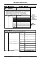
Name Description Values Meaning
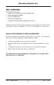
CALCAL
Calibration
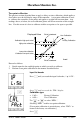
In this mode you can
1. Calibrate the instrument using a mV source - rcAL or ref source cal.
2. Offset the calibration to account for errors in actual sensor
measurement and a ref sensor - UCAL or user calibration
3. Return to factory set calibration - FACT or factory set calibration.
rcAL
Calibration
point
nonE
No calibration
PV
Calibrate main Process Value input.
PV.2
Calibrate DC input, or PV 2.
1A.Hi
Calibrate DC output high - Module 1
1A.Lo
Calibrate DC output low - Module 1
2A.Hi
Calibrate DC output high - Module 2
2A.Lo
Calibrate DC output low - Module 2
3A.Hi
Calibrate DC output high - Module 3
3A.Lo
Calibrate DC output low - Module 3
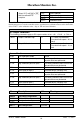
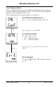
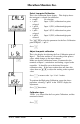
INPUT CALIBRATION
For ‘CAL’ = ‘PV’, or ‘PV.2’, the following parameters apply.
PV
PV Calibration Value
IdLE
Idle
mv.L
Select 0mV as the calibration
point
mv.H
Select 50mV as the calibration
point
V 0
Select 0Volt as the calibration
point
1. Select calibration value
V 10
Select 10V as the calibration
point
2. Apply specified input
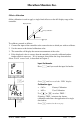
CJC
Select 0
o
C CJC calibration point
3. Press to step to ‘GO’
rtd
Select 400Ω as the calibration
point
HI 0
High impedance: 0Volt cal’n
point
HI 1.0
High impedance: 1.0 Volt cal’n
point
See Note below.
FACt
Restore factory calibration
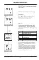
GO
Start calibration
no
Waiting to calibrate PV point
Goto User
calibration
table-See also
chapter 7
Go to input
Calibation table
Go to
DC Output
Calibration
table