
Computer Monitor User Manual

Marathon Monitors Inc.
AACC 2000 Carbon Nov. 1, 1997
61
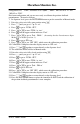
configuration list. ‘func’ should be set to ‘Vpos’, ‘VAL.L’ must be set to ‘0’ and
‘VAL.H’ to ‘100’.
Exit from configuration and you are now ready to calibrate the position feedback
potentiometer. Proceed as follows.
1. In Operator level, press the AUTO/MAN button to put the controller in Manual mode.
2. Drive the valve to its fully open position using .
3. Press until you get to ‘ip-List’.
4. Press to get to ‘PCAL-OFF’.
5. Press or to turn ‘PCAL’ to ‘on’.
6. Press and the upper readout indicates ‘Pot’.
7. Press or to get to ‘Pot-3A.Hi’. (Assuming that the Potentiometer Input
Module is in module position 3.)
8. Press to go to ‘GO-no’.
9. Press or to see ‘GO-YES’, which starts the calibration procedure.
10. Calibration is complete when the display returns to ‘GO-no’.
11. Press and together to return directly to the Operator level.
12. The controller should still be in Manual mode.
13. Drive the valve to its fully closed position using .
14. Press until you get to ‘ip-List’.
15. Press to get to ‘PCAL-OFF’.
16. Press or to turn ‘PCAL’ to ‘on’.
17. Press and the upper readout indicates ‘Pot’.
18. Press or to get to ‘Pot-3A.Lo’
19. Press to go to ‘GO-no’.
20. Press or to see ‘GO-YES’, which starts the calibration procedure.
21. Calibration is complete when the display returns to ‘GO-no’.
22. Press and together to return directly to the Operator level.
23. Press the AUTO/MAN button to place the controller in AUTO and the calibration of
the position feedback potentiometer is now complete.