1010-1007, Rev.
ii COPYRIGHT NOTICE This manual is a publication of Maple Systems, Inc., and is provided for use by its customers only. The contents of the manual are copyrighted by Maple Systems, Inc.; reproduction in whole or in part, for use other than in support of Maple Systems equipment, is prohibited without the specific written permission of Maple Systems. The copyright of EasyBuilder-5000 and its related software belongs to Weintek Labs, Inc.
iii Table of Contents Connecting to COM1 and COM2 on Port B ..............24 COPYRIGHT NOTICE ....................................................... ii WARRANTY .................................................................... ii IF SERVICE IS REQUIRED ................................................ ii Connecting multiple PLC/controllers serially using daisy chaining ...........................................................25 APPLICATIONS ASSISTANCE ...........................................
iv EZware5000 Series Programming Manual Chapter 6 – Using EZware-5000 .................................... 52 Creating a Frame ....................................................122 Overview ..................................................................... 52 Window Background ..............................................122 The Project Manager ................................................... 52 Deleting a Window ....................................................
v Using Alarms .............................................................. 168 Monitoring Alarms with the Alarm (Event) Log ..... 168 Displaying Alarms using the Alarm Display Object 171 Displaying Alarms using the Alarm Bar Object ...... 173 Using Events .............................................................. 174 Monitoring Events with the Event Log Object ....... 174 Displaying Events Using the Event Display Object . 174 Chapter 12 – Security .................................................
This page intentionally left blank 1010-1007, Rev.
Introduction 1 Chapter 1 – Introduction Welcome Welcome to the Maple Systems’ HMI5000 Series Human Machine Interfaces (HMIs). Using graphic HMIs has never been easier. This powerful family of graphic HMIs connects to programmable logic controllers (PLCs) to provide the human-machine interface in industrial applications. The HMI5000 Series has several features not found in other graphic HMIs.
2 EZware5000 Series Programming Manual In most cases, we will describe each method when the task is first discussed. The menu method is then used whenever the task is used in later procedures. Other conventions used in this manual are listed in the following table. Convention Bold Meaning Characters that you must type exactly as they appear. For example, if you are directed to type a:\setup, you should type all the bold characters exactly as they are printed.
Introduction 3 OIT/HMI Basics Operator Interface Terminals (OITs) and Human Machine Interfaces (HMIs) provide much more versatility than traditional mechanical control panels. An OIT allows a plant floor operator to monitor current conditions of a control system and, if necessary, to initiate a change in the operation of the system. OITs connect to programmable logic controllers (PLCs) typically through the PLC’s serial communications port.
4 EZware5000 Series Programming Manual Graphics Object A Graphics Object is any text, icon, or picture that can be displayed on the HMI. Graphics objects are further defined by how they are composed or created. A Text Object is a graphics object that displays text on the HMI screen. A Bitmap Object is a graphics object that displays a bitmap on the HMI screen. Bitmaps are files stored in the HMI to display pictures. A Shape Object is a graphics object that displays a shape on the HMI screen.
Introduction 5 List of Features The next chapter will guide you through the creation of your first project. Before you proceed, you may wish to read this brief list of some of the features offered in the EasyBuilder-5000 programming software. Bit Lamp Creates a graphic object to reflect the current status of a PLC bit. Word Lamp Creates a graphics object to reflect the current state of a multi-state PLC data register. Set Bit Creates a touchscreen graphics object that represents a two-state switch.
6 EZware5000 Series Programming Manual Video In Input and play video on the HMI from an external source (X-models only). Bar Graph Creates a bar graph with alarm monitoring. Meter Display Creates a scale meter. Trend Display Creates a trend graph. Samples data in single or multiple 16-bit PLC registers and plots the data on a time graph. History Data Display Displays historical data in a tabular format. Data Block Display Displays the data stored in a series of registers as a line graph.
HMI Local Setup 7 Chapter 2 – HMI Local Setup Factory Configuration Each HMI arrives from the factory with a demo project file that illustrates some of the most popular features of the HMI. For a first time user, it is worthwhile to navigate through the screens in the demo project and become familiar with the features and capabilities of the HMI and EZware-5000. Refer to the EasyBuilder-5000 Help file for more information about the features and operation of the HMI and EasyBuilder-5000.
8 EZware5000 Series Programming Manual The X-models (HMI5104XH, HMI5121X, and HMI5150X) have an additional icon in the System Setup Toolbar for Screen Calibration. Older Models Newer Models Touch Panel Calibration Changing the System Settings To change the system settings on the HMI: 1. Open the System Setup Toolbar as described above, and click the System Settings icon. 2. A dialog will be displayed requesting the Local password. The default password is 111111. 3.
HMI Local Setup 9 6. If using a static IP address, use the IP Address get from below option. The IP fields are enabled. Enter the appropriate settings for your network. 7. Click the Time/Date tab to configure time/date settings. The time/date dialog is displayed. 8. Configure appropriate time and date settings. 9. Click on the Security tab to display the security settings dialog. Here, you can select your system passwords. 1010-1007, Rev.
10 EZware5000 Series Programming Manual 10. Configure your password settings. Local Password The password required to enter local setup. Upload Password The password required to upload data from the HMI to a PC or memory module. Download The password required to download data to the HMI from a PC or memory module. Password Upload (History) The password required to upload history files from the HMI to a PC or Password memory module. 11. The new password must be entered, and then entered again to confirm.
HMI Local Setup 11 13. Click on the HMI name tab to give the HMI a unique name. This name can be used to address the HMI for downloading over Ethernet. Downloading by name is supported only on the HMI5070TH and HMI5100TH, with Firmware version 20091002 or later. 14. Click the Firmware setting tab to access the Upgrade firmware option and the Portrait Mode settings (for models with the Portrait feature).
12 EZware5000 Series Programming Manual 15. Click the VNC server setting tab to enable remote access using VNC (Virtual Network Computing). Click Start VNC to enable the VNC server. Click the VNC login password to enter the password used to login to the HMI with a remote VNC viewer. The default password is 111111. Click Apply and then click OK to save the settings and exit the System Settings window. The VNC option is only available on Ethernet-equipped models. 16.
HMI Local Setup 13 The Popup download window option allows you to turn on or off whether the Download dialog window appears on the screen when a USB flash drive is connected to the USB port on the HMI. The Restart after download/upload option causes the HMI to reboot after a download or upload from a USB flash drive or SD card, when selected. 17. Click on the CF Card tab to display the CF card dialog (only CF Card equipped models). The CF Card tab displays information about the Compact Flash module.
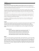
14 EZware5000 Series Programming Manual 3. Click on the Version tab to display the current firmware information. Transferring Projects and Data from USB/CompactFlash When a USB or Compact Flash device is inserted into the HMI5000 Series, a dialog is displayed. The same dialog is displayed for transferring projects or data. Data is placed on the USB or CF device by EasyBuilder or Project Manager. Download Upload Restart Project and exit Cancel Time Remaining 1010-1007, Rev.
HMI Local Setup 15 When Download is selected, a dialog will appear requesting the Download password and what data to download. Password Download project files Download history files Clear history files Enter the Download password. When checked, the HMI will check the specified folder for project data, and transfer it if it exists. When checked, the HMI will check the specified folder for history data, and transfer it if it exists (includes data log files, event log files, and recipe files).
16 EZware5000 Series Programming Manual Chapter 3 – Connect the HMI to the PLC or Controller The HMI5000 Series family of HMIs can connect to one, two, or more PLC/controllers. This is accomplished via two 9pin D-sub serial communications connectors (Port A and Port B) and one Ethernet port. Each PLC/Controller has its own wiring requirements. Maple Systems offers HMI-to-PLC/Controller communication cables for most PLC/Controllers that are built to any length and tested for high reliability.
Connect the HMI to the PLC or Controller 17 Figure 3: COM Ports for the HMI5070NH/TH, HMI5100N/T, HMI5104TH/HMI5104XH/HMI5121X/HMI5150X 1010-1007, Rev.
18 Figure 4: COM Ports for the HMI5056N 1010-1007, Rev.
Connect the HMI to the PLC or Controller 19 Figure 5: COM Port for the HMI5043N/T 1010-1007, Rev.
20 EZware5000 Series Programming Manual Connecting to COM1 and COM3 on Port A Maple Systems HMI5000 Series family of HMIs is capable of connecting to multiple PLC/controllers. If you choose to take advantage of this feature, and one of your PLC/controllers uses either RS485-4 Wire or RS485-2 Wire communication, one of four splitters will be needed. Scenario 1 – Two RS485 2 Wire PLC/Controllers, with COM1 configured for RS485-2 Wire and COM3 configured for RS485-2 Wire. 1010-1007, Rev.
Connect the HMI to the PLC or Controller 21 Scenario 2 – One RS485 2 Wire PLC/Controller with COM3 configured for RS485-2 Wire and one RS485 4 Wire PLC/Controller with COM1 configured for RS485-4 Wire. 1010-1007, Rev.
22 EZware5000 Series Programming Manual Scenario 3 – One RS485 4 Wire PLC/Controller with COM1 configured for RS485-4 Wire and one RS232 PLC/Controller with COM3 configured for RS232. 1010-1007, Rev.
Connect the HMI to the PLC or Controller 23 Scenario 4 – One RS485 2 Wire PLC/Controller with COM1 configured for RS485-2 Wire and one RS232 PLC/Controller with COM3 configured for RS232. 1010-1007, Rev.
24 Connecting to COM1 and COM2 on Port B Two RS232 PLC/Controllers, with COM1 and COM2 configured for RS232. 1010-1007, Rev.
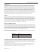
Connect the HMI to the PLC or Controller 25 Connecting multiple PLC/controllers serially using daisy chaining The RS485 4-wire and RS485 2-wire communications ports of the HMI5000 Series family support multi-drop connections. A daisy-chain connection is made from the HMI to the first PLC/controller, and then from the first PLC/controller to the second and so on (see below). The network may need biasing resistors – refer to the PLC/controller documentation for more information.
26 EZware5000 Series Programming Manual Troubleshooting The HMI must be connected to a PLC/controller in order for the project to run correctly in the HMI. If there is a problem with communications between the HMI and PLC/controller, the “PLC no response” message (window 5) will appear on the screen and objects addressing PLC registers will not appear on the screen. Here are some things to check if this occurs: 1.
Creating a Sample Project 27 Chapter 4 – Creating a Sample Project Often the best way to learn about new software is to jump right in and begin using it. This chapter will step you through the process of creating a sample project that can be downloaded to your HMI.
28 EZware5000 Series Programming Manual 2. Click New… The Select Window Style dialog box appears. 3. Click Base Window. The Window Settings dialog box appears. 4. Type “Bargraph” in the Name field. The number 11 should already be in the Window No. field. 1010-1007, Rev.
Creating a Sample Project 29 5. Click the box for the Background color. The color palette box opens. Click on the white color box in the lower-right corner. The color box will reflect the color that you have selected. 6. Click OK. Highlight Window 11: Bargraph in the Open Window list, then click the Open button. Window 11 now appears on your work area. Now let’s create a function key to open Window 11 from the initial screen, Window 10. To create a Function Key: 1.
30 EZware5000 Series Programming Manual 5. Select shape number 7 and click OK. The Function Key Object’s Shape tab now shows a preview of how the function key will appear on the screen. Click OK. 6. On the main screen of EasyBuilder you will see a white rectangle outline that is attached to your cursor in the work area. This represents the function key just created. Click to place the function key in the middle of Window 10.
Creating a Sample Project 31 7. In the top menu bar in EasyBuilder 5000, click Draw > Text (or select the Text Tool icon in the Draw Toolbar). In the New Text Object properties window, select Arial in the Font box and 16 pt in the Size box. Click the Color box and the color palette box opens. Click on the white color box in the lower-right corner. The color box will reflect the color that you have selected. 8. In the Content box at the bottom of the properties window, type To next window and click OK.
32 EZware5000 Series Programming Manual Now let’s create a bargraph on Window 11. We will use the bargraph to indicate the level of a tank. We will create pushbuttons to increase or decrease the level of the tank by turning a pump on and off. To open Window 11, select Window > Open Window and double-click Window 11 in the list. Alternatively, doubleclick on Window 11 in the Windows Option list on the left side of the EasyBuilder screen. To create a Bargraph: 1.
Creating a Sample Project 33 3. Click the Outline tab. In the Attribute section, select the following: Type: Normal Direction: Up Zero: 0 (the register value represented when the bargraph is minimum) Span: 100 (the register value represented when the bargraph is maximum) Bar width ratio (%): 30 4. In the Bar color/style section, click the Transparent checkbox. Leave the Bar and Bar style colors at their default blue. 5. Leave the Target indicator Enable box unchecked. 6.
34 EZware5000 Series Programming Manual 8. Click the Picture Library… button and select the Tanks1 library. If it does not appear in the Library list on the left side of the Picture Library window, click the Select Lib… button and locate Tanks1.flb in the Library folder. Select it and click Open to add it to the list. 9. Select picture number 24 and click OK. This is the picture that will appear over the bargraph on the screen. 1010-1007, Rev.
Creating a Sample Project 35 10. Click OK to accept the properties settings. On the main screen of EasyBuilder you will see a white rectangle outline that is attached to your cursor in the work area. Click to place the Bargraph Object in the middle of Window 11. You can click and drag it to adjust its position once you have placed it on the window. Next we will create a pushbutton to raise the level of the tank and another one to lower the level of the tank.
36 EZware5000 Series Programming Manual 3. In the Attribute section, select the following: Set Style: Press and hold increment (JOG++) (this will cause the value in the register to increase while the button is pressed) Inc. value: 1 Upper limit: 100 JOG delay: 0.5 second(s) JOG speed: 0.1 second(s) 4. Click the Shape tab. Click the Use Shape checkbox and click the Shape Library… button. Select the Arrows 1 library.
Creating a Sample Project 37 12. Click OK and place the Set Word Object below the bargraph on Window 11 in EasyBuilder. You can click and drag it to adjust its position once you have placed it on the window. 13. Click on the screen to deselect the Set Word Object, then double-click on it to reopen the properties (or right-click on it and select Attribute) and click the Profile tab (the Profile tab is not available when creating a new object). Set the Width and Height to 60 (pixels). 14.
38 EZware5000 Series Programming Manual 16. Paste the Set Word Object to the window (Edit > Paste or Ctrl+V) and drag it next to the other Set Word Object. 17. Click on the screen to deselect it, then double-click on the new Set Word Object to open the Properties window (or right-click on it and select Attributes). 18. In the Set Word Object’s Properties General tab, you can enter a description of the object such as Tank Level Down. Select LW for the Device Type and 0 for the Write address.
Creating a Sample Project 39 19. In the Attribute section, select the following: Set Style: Press and hold decrement (JOG--) (this will cause the value in the register to decrease while the button is pressed) Dec. value: 1 Bottom limit: 0 JOG delay: 0.5 second(s) JOG speed: 0.1 second(s) 20. Click the Shape tab. Click the Shape Library… button. Select the Arrows 1 library. Select shape number 8 and click OK. 21. Click OK to accept the properties settings.
40 EZware5000 Series Programming Manual 3. In the Blinking section, select None for the Mode. 4. Click the Shape tab and check the Use Picture checkbox (uncheck the Use Shape checkbox if it is selected). 5. Click the Picture Library… button and select Pumps1 in the Library list. If it does not appear in the Library list on the left side of the Shape Library window, click the Select Lib… button and locate Pumps1.flb in the Library folder. Select it and click Open to add it to the list.
Creating a Sample Project 41 6. Click OK and place the Bit Lamp Object to the left of the tank. You can click and drag it to adjust its position once you have placed it on the window. 7. Click on the screen to deselect the Bit Lamp Object, then double-click on it to reopen the properties (or rightclick on it and select Attribute) and click the Profile tab. Set the Width and Height to 50 (pixels). 8. Click OK to accept the new Profile properties. 9.
42 EZware5000 Series Programming Manual 11. Click the Profile tab and set the Width to 100 and the Height to 25 (pixels). 12. Click OK to accept the properties. Click to place the Bit Lamp Object between the pump and the tank. You can click and drag it to adjust its position once you have placed it on the window. Now we will create a Set Bit Object to turn the pump and pipe on and off whenever the Up or Down Arrows (Set Word Objects) are pressed. To create a Set Bit: 1.
Creating a Sample Project 3. 43 Click the Shape tab and deselect the Use Shape checkbox. This will make the Set Bit invisible on the screen. 1010-1007, Rev.
44 EZware5000 Series Programming Manual 4. Click OK and place the Set Bit Object on the window. It will appear as a square frame. Click on the screen to deselect it, then double-click on it to reopen the properties (or right-click on it and select Attribute). Click the Profile tab and set the Width and Height to 65 (pixels). Click OK to accept the new Profile settings. 5. Move the Set Bit Object over the Arrow Up button. 6.
Creating a Sample Project 45 2. Use the drop-down menus to locate the project folder in EZ5000. 3. In the File name text box, type Sample_Project.mtp. 4. Click Save. The file is saved onto your computer hard drive and the main screen of EasyBuilder reappears. Compiling your first project 1. From the Tools menu, click Compile. The Compiling dialog box appears. 2. Click the Compile button. EasyBuilder will compile your project and display error results. 3. If no errors occur, click Close.
46 EZware5000 Series Programming Manual 2. Click the arrow button to go to the next window. 3. Click and hold the arrow UP button to fill the tank. The pump turns green and the pipe starts blinking. The bargraph is yellow when the tank begins to fill and turns blue when it fills more than 25%. 4. When the tank fills above 85% the bargraph turns red. 5. Click and hold the arrow DOWN button to lower the tank level. 6. Right-click in the simulation window and select Exit simulation. 1010-1007, Rev.
Creating a Sample Project 47 Downloading your first project First, connect a +24 VDC power supply to the HMI. Refer to the HMI5000 Series Installation Guide for more information. In order to download your project, you must first connect the HMI to your computer. There are two methods of downloading to the HMI, Ethernet or USB, depending on your model.
48 EZware5000 Series Programming Manual 2. Connect the HMI to your computer using the USB configuration cable (PN 7431-0115). 3. Select Tools > Download from EasyBuilder’s menu (or click the Download icon). 4. Make sure that the USB, Firmware, and Reboot HMI After Download boxes are checked. 5. Click the Download button. If the HMI is properly connected to the PC, the status box on the download dialog will update with messages indicating the progress of the transfer.
Simulator Mode 49 Chapter 5 – Simulator Mode As you saw from creating the sample project in the last chapter, downloading any changes you make to the HMI can take time. To decrease the amount of time required to download a project to the HMI, you can uncheck the Firmware option on EasyBuilder's download dialog once you have downloaded it once. A better way of testing changes made to a project is to use the computer to simulate the operation of the HMI.
50 EZware5000 Series Programming Manual Off-line simulation is also great for demonstrating the operation of the HMI and becoming familiar with the operation of the HMI before it is installed. If you want to simulate the interaction with a PLC when off-line, it can be done by creating additional windows on the HMI which allow PLC data input. To use off-line simulation mode from EasyBuilder: 1.
Simulator Mode 2. Click Online-Simulator. The Open Project dialog box appears. 3. Click on the compiled project file that you wish to simulate. 4. Click Open. The simulation screen appears. 5. To end on-line simulation, right click in the simulation screen and click Exit. 51 The above method will work with a standard PC serial COM port, regardless of the COM number assigned to the PC serial port. EasyBuilder supports RS232 communication on ports COM1 – COM9.
52 EZware5000 Series Programming Manual Chapter 6 – Using EZware-5000 Overview The EZware-5000 software is composed of three separate applications that are accessible from the EZware-5000 folder: EasyBuilder, Project Manager, and EasyConverter. EasyBuilder is the application software used to create a project file. Project Manager is a utility application that puts the HMI into different operating modes. EasyConverter changes certain binary files created by the HMI into text files.
Using EZware-5000 53 HMI IP, Password Settings Settings Button Click the Settings button to view the Download/Upload passwords (default 111111). These must match the Download/Upload passwords in the HMI’s System Settings Toolbar. Reboot HMI Connects to the HMI, checks password and resets the HMI in order to update system files. Connection Setting Select between Ethernet or USB cable (depending on model) for communication between the computer and HMI.
54 EZware5000 Series Programming Manual EasyBuilder-5000 Development Window Objects Summary EasyBuilder includes several active graphics objects that are used to represent data that is stored in the PLC or internal memory of the HMI. The data represented can be single bit coils, 16-bit, 32-bit, or 64-bit registers. The data can be represented as numbers, ASCII characters, or as graphic shapes or bitmap images. This section provides a summary of all the objects available in EasyBuilder-5000.
Using EZware-5000 55 Set Bit The Set Bit Object is used as a button to toggle ON or OFF the state of a bit or coil in the PLC, or a bit in the HMI local memory (LB). There are a number of different options (Set Styles) available to operate the button including touch (On, Off, Toggle, Momentary), window open or closed, and backlight on or off. Set Word The Set Word Object is used as a button to change the value in a PLC register, or the value in a register in the HMI local memory (LW).
56 EZware5000 Series Programming Manual Function Key The Function Key Object is used to change windows, popup a window, return to a previous window, close a window, or input data as part of a keypad. It can also be used to execute a macro or print the screen to a USB flash drive, SD card, or printer. Numeric Display The Numeric Display Object is used to display the current value in a register. The value can be displayed as BCD, Hex, Binary, or Decimal (signed or unsigned).
Using EZware-5000 57 Moving Shape The Moving Shape Object is used to move a shape or picture on the screen based on values in consecutive registers (specified by the Read Address). The value in the Read Address register determines the state of the object and can be used to change its appearance. The value in the next consecutive register(s) determines the position of the part (relative to the object’s initial position, in pixels).
58 EZware5000 Series Programming Manual Recommended Format and Resolution 100% (1:1) 50% (1:2) NTSC 720 x 480 360 x 240 PAL 720 x 576 360 x 288 A capture function allows capturing video images and storing them as *.jpg files on a USB flash drive or SD card. The video capture is triggered by a PLC or local bit (OFF > ON) and can be configured to capture video once per second for a period of time defined by the Record time.
Using EZware-5000 59 History Data Display The History Data Display Object is used to display historical data collected by the Data Sample Object in a table format. Up to 16 channels of data can be displayed from consecutive addresses, and can be any mix of data types (e.g., 16-bit unsigned, 16-bit signed, 32-bit float, etc.). Note: The History files section in the Data Sampling Object must have a box checked (e.g.
60 EZware5000 Series Programming Manual The number of data points must be stored at [control word address + 1], and the data must be stored starting at [Data storage start address] before the control value is written to the Control Word address.
Using EZware-5000 61 The Read address field is the starting address of the data to plot. Each channel has its own Read address. Normally, the X and Y data are read from two consecutive addresses beginning with the Read address. To have the XY Plot use separate addresses for X and Y data, check the Separated address for X and Y data checkbox. Separating the X and Y data addresses also allows the X and Y data to have different formats.
62 EZware5000 Series Programming Manual Line: The data is plotted as a Line graph, with squares plotted at each data point. Point: The data is plotted as squares at each data point. X-axis projection: The data is plotted as a line graph (no squares). The plot is filled along the X-axis. Y-axis projection: The data is plotted as a line graph (no squares) with the X and Y data transposed. The plot is filled along the Y-axis.
Using EZware-5000 63 to display (including the starting day). If three days are selected, but only two event files are included within the three day period, only two event files will be displayed. With Index of the last history selected, the value entered in the History control register determines the starting day (most recent, where 0 = today) and the value in the History control register + 1 is the number of event files to display.
64 EZware5000 Series Programming Manual Backup The Backup Object is used to copy recipe files (*.rcp), event files (*.evt), and data files (*.dtl) from the HMIs internal memory to a USB flash drive, SD card, or a PC connected via Ethernet. When Historical event log or Historical data log is selected, the historical event logs or data logs can be saved in their native file formats (*.evt or *.dtl respectively) or in *.csv format.
Using EZware-5000 65 Trigger address + 1 Number of words to transfer (32 words maximum) The number of words to transfer from the PLC to the HMI or HMI to PLC. Trigger address + 2 PLC Data Address Offset The Address Offset (from the Trigger address + 4) at which the transfer of data to/from the PLC will start. Trigger address + 3 HMI Data Address Offset The Address Offset at which the transfer of data to/from the HMI will start.
66 EZware5000 Series Programming Manual Note: When transferring bits, bits can only be transferred to the local HMI’s internal memory. It is not possible to transfer bits to a remote HMI or another PLC. Data Sampling The Data Sampling Object is used to create Data Logs. A Data Log gathers data that can be saved as History files to the HMIs internal memory, or to a compact flash, SD card, or USB drive (depending on the model).
Using EZware-5000 67 Action modes include Bit ON, Bit OFF, or Word write. Bit ON: Start action sets the Action address bit. End action clears the Action address bit. Bit OFF: Start action clears the Action address bit. End action sets the Action address bit. Word write value settings – Constant: Start action writes the Start value into the Action address register. End action writes the End value into the Action address register.
68 EZware5000 Series Programming Manual Time setting address + 8 End time (hour) This register determines the hour the End Action is executed. Range is 0-23. Time setting address + 9 End time (minute) This register determines the minute the End Action is executed. Range is 0-59. Time setting address + 10 End time (seconds) This register determines the second the End Action is executed. Range is 0-59.
Using EZware-5000 69 Managing Projects Like most Windows™ application software, EasyBuilder will open, save, close, and print files using the standard windows format. Opening, Editing Projects To create a new project 1. On the File menu, click New or click the New icon in the Standard toolbar. The EasyBuilder dialog box appears. 2. Select the HMI model that you intend to use with your project and whether you want to use the HMI in Landscape or Portrait mode (if available for your model).
70 EZware5000 Series Programming Manual 3. Enter a file name and then click Save. 4. The main screen of EasyBuilder reappears. To save a project using the compress feature: The compress feature allows you to save a project in compressed format so that the project data takes less space on your hard drive. This utility also will save the graphics libraries associated with the project into the compressed file.
Using EZware-5000 71 Note: It is a good idea to backup your Library folder before uncompressing a *.cmp file because the uncompress utility will overwrite any existing library files with the same name. You also have the option not to overwrite existing files, and in most cases this is okay unless the project being uncompressed uses modified libraries with the same names as the standard libraries in the Library folder.
72 EZware5000 Series Programming Manual 2. The Object List combines a list of all of the windows in a project, and all of the objects on each window, into a single tree. Notice that the tree displays the title for each window next to the window number. This makes it easy to determine the windows that have been created for a project. An asterisk (*) next to a window indicates that the window is currently open. 3. To display an open window, click on the window number in the Window Tree.
Using EZware-5000 73 Using the Window Tree to change object attributes 1. On the Window Tree, click + adjacent to any window number. The tree will expand to list the objects on that window, as shown: 2. The Object ID of each object will be listed. For example, TX_0 is Text Display #0, ND_0 is Numeric Display #0, etc. 3. To highlight a particular object on the screen, click on the Object ID in the list.
74 EZware5000 Series Programming Manual If you still don’t see the grid after you have enabled it, make sure that the color of the grid doesn’t match the background color of the window currently displayed. Changing the grid size and color: 1. On the Option menu, click Grid/Snap. 2. Select the X spacing and Y spacing for grid size. Spacing is measured in pixels. 3. Select the Grid color in the drop down menu.
Using EZware-5000 75 To zoom in on the selected window 1. Use the zoom pull-down menu in the Edit Toolbar. Zoom levels range from 50% to 200% in 25% increments. 2. On the View menu, select Zoom Level. Zoom levels range from 50% to 200% in 25% increments. Another option is to display what are known as Object ID tags. Every time you create a new object in EasyBuilder, an Object ID tag is assigned to the new object.
76 EZware5000 Series Programming Manual Basic Editing Commands To select a graphics object 1. On the Edit Menu, click Select or click the mouse cursor icon in the Draw Toolbar. 2. Click on the graphics object. This causes the text box to be selected, with small square blocks around the edges indicating the boundaries of the object. Deselect the object by clicking somewhere else in the work area. 3.
Using EZware-5000 77 3. From the Edit menu, click Undo or click the Undo icon from the Standard Toolbar. You can also press CTRL+Z. The deleted text box reappears. 4. The Redo command is used to cancel the Undo command. Using the Cut , Copy , and Paste commands 1. These commands are all selected from the Edit menu. 2. Select the graphics object or objects you wish to cut or copy. 3.
78 EZware5000 Series Programming Manual Multiple objects can be created according to these parameters: Pitch vs. Interval: This setting affects how EasyBuilder places the copies of an object on the screen relative to each other. The Pitch setting will interpret the X Distance setting as the distance from the left side of an object to the left side of the next object and the Y Distance setting as the distance from the top of one object to the top of another object.
Using EZware-5000 79 4. In the Destination box, enter the number of the window in the current project that you wish to copy the selected window(s) to. If multiple windows are selected, they will be copied into consecutive windows beginning with the one designated in the Destination window. 5. Click OK. The EasyBuilder Destination window is redisplayed with the Window Copy command executed. To delete a graphics object(s) 1. Select the object or objects you wish to delete. 2.
80 EZware5000 Series Programming Manual 4. All of the objects that use PLC data registers or the internal memory of the HMI are listed in this dialog box according to their Object ID tag. Alongside each ID tag is the PLC or HMI memory identifier. Grouping Objects When creating graphics on a window, you may create a complex graphic that is actually composed of several simpler objects grouped together. Grouping objects together makes it easier to move or copy multiple objects at the same time.
Using EZware-5000 Bottom Layer: Send the selected object to the bottom layer. Previous Layer: Next Layer: 81 Moves the selected object to the previous layer. Moves the selected object to the next layer. Normally, an object that is controlled by a PLC Register (i.e., a Word Lamp, Bit Lamp, Animation, etc.) is brought to the Top Layer when the value in the PLC Register changes. This behavior can be changed by the Object Layout option on the General tab of the System Parameters dialog.
82 EZware5000 Series Programming Manual To make objects the same size : 1. Select the objects you wish to make the same size. 2. From the Edit menu, select Make Same Size, then Both or click the Make Same Size icon from the Edit toolbar. Making Objects the Same Color This feature can be used to make two or more drawn objects the same color. To make objects the same color 1. Select the objects that you wish to make the same color. EZware will choose the color of the last selected object. 2.
Using EZware-5000 To rotate objects 83 : 1. Select the object you wish to rotate. 2. From the Edit menu, select Flip/Rotate > Rotate 90 Degrees or click the Rotate icon from the Edit toolbar. To lock an object : Each object position and size can be locked by using the Pin button. When the object is locked, its position and size cannot be changed. 1. Select the object you wish to lock. 2. From the Edit menu, select Pinned or click the Pinned icon from the Edit toolbar. 3.
84 EZware5000 Series Programming Manual System Parameter Settings The final section of this chapter shows all the settings or parameters that can be configured using EasyBuilder. From the Edit menu, select System Parameters. The System Parameter Settings dialog box appears. The dialog box has eight tabs: Device, Model, General, System Setting, Security, Font, Extended Memory, and Printer/Backup Server. 1010-1007, Rev.
Using EZware-5000 85 To configure Device tab settings: 1. Click the New… button. The Device Properties dialog appears. You can “export” a project created for one PLC brand to a different PLC brand by loading the project file into EasyBuilder, then entering a different PLC type in this box.
86 EZware5000 Series Programming Manual 6. Select the PLC station number for your PLC if appropriate (see Controller information Sheet for your PLC) and then click Settings… The COM Port Settings dialog appears. 7. Select the appropriate COM port. This is the COM port used by the HMI. 8. Select Baud rate, Data bits, Parity and Stop bits. Use Maple Systems’ Controller Information Sheets or the PLC manufacturer’s operations manual for information on the communications parameters required by the PLC.
Using EZware-5000 87 To configure the Model tab settings: 1. HMI model: Select the HMI model that you are programming. 2. HMI station no.: When multiple HMIs are used, this selects the unique network address of the HMI. See Controller Information Sheet for more information. 3. Port No: Assign a TCP/IP port so that another HMI can access this port. For more information, select Help > Help Topics > How Do I…Setup TCP Port Forwarding With the HMI. 4.
88 EZware5000 Series Programming Manual Auto Resizing Using the Model Tab This tab can be used to automatically resize your project when changing to another HMI model with a different size touchscreen. The project and all objects and graphics will be proportionately resized automatically. To auto resize your project using the Model tab in the System Parameters dialog: 1. In the Model tab, select a different display size from the HMI model drop-down box and click OK. 2.
Using EZware-5000 89 To configure General tab settings: 1. Fast selection button: The Attribute: drop-down enables or disables the fast selection button, which is used to open the Fast Selection window (window number 3). The Settings button sets the look of the button including shape and color. The Position drop-down sets the fast selection button on either the lower left or lower right portion of the display.
90 EZware5000 Series Programming Manual 3. Options: The Startup window no. selects the window number that will be displayed every time the HMI is started up. Window 10 is the default startup window. The Common window determines if objects in the common window (window 4) are placed above or below the base window. The Object layout drop-down determines the layout and display of objects by selecting either Control mode or Nature mode. Normally, an object that is controlled by a PLC Register (i.e.
Using EZware-5000 91 To configure System Setting tab settings: 1. Startup language after redownloading the project: Select the language that the HMI is to use when restarting after a download. 2. Execute init. MACRO when power on: When checked, the HMI will execute the selected macro on startup. Available only when one or more macros exist in the project. 3.
92 EZware5000 Series Programming Manual 6. Disable buzzer: When checked, the HMI will not sound the buzzer (beep) when the screen is touched. Local Bit LB9019 can be used to control the buzzer. Set the bit to disable the buzzer and clear the bit to enable the buzzer. 7. Prohibit remote HMI connecting this machine: When checked, the HMI will not allow connections from a remote HMI. Local Bit LB9044 can be used to control remote connections.
Using EZware-5000 93 To configure Security tab settings: The Security tab is used to set up a table of users, user levels (access classes), and passwords. Up to 12 users can be individually enabled, and each has a unique password and combination of any six access classes (A-F). Only numbers are allowed for password. When an object is created, it can be assigned an access class (A-F).
94 EZware5000 Series Programming Manual The object can be configured to handle insufficient security in one of two ways: The object can be hidden while security is not sufficient. The HMI can display the message defined as Message 1 in the System Message object. There are a number of local HMI addresses that can be used with the security features. Address Description LB9050 Reset security level to 0 (no security) Boolean Set momentarily to trigger.
Using EZware-5000 LW9500, LW9501 LW9502, LW9503 LW9504, LW9505 LW9506, LW9507 LW9508, LW9509 LW9510, LW9511 LW9512, LW9513 LW9514, LW9515 LW9516, LW9517 LW9518, LW9519 LW9520, LW9521 LW9522, LW9523 95 New password, user 1 32-bit unsigned New password, user 2 32-bit unsigned New password, user 3 32-bit unsigned New password, user 4 32-bit unsigned New password, user 5 32-bit unsigned New password, user 6 32-bit unsigned New password, user 7 32-bit unsigned New password, user 8 32-bit unsigne
96 EZware5000 Series Programming Manual To configure Font tab settings: Determines the font for non-ASCII strings. To add a Windows TrueType font that is on your computer, click Add... and select the font from the drop down menu that appears, and click OK. 1010-1007, Rev.
Using EZware-5000 97 To configure the Extended Memory tab settings: The Extended Memory tab is used to configure the extended memory for saving data to an SD card or USB flash drive (only USB1 can be used). There are 10 files that can be configured for saving data, em0.emi through em9.emi. Each extended memory location can be accessed using the Device Type setting in an object’s properties.
98 EZware5000 Series Programming Manual To configure Printer/Backup Server tab settings: 1. Check the Use Remote Printer/Backup Server checkbox to enable the HMI to print to a printer connected to a PC on the network. The EasyPrinter utility (included with EZware-5000 and accessible through Project Manager) must be running on the PC with the network printer connected. 2. In the Output settings section, select page layout (horizontal or vertical), print area size, and margins. 3.
Using EZware-5000 99 Automatically Reboot HMI EasyBuilder can automatically reboot the HMI after download. To enable automatic reboot of HMI after download: 1. From the Tools menu, select Download. The Download dialog box is displayed. 2. Check the Reboot HMI after download checkbox. 3. Click OK. Save and Compile the Project EasyBuilder can automatically save and compile the project when downloading or simulating. To enable automatic save and compile 1.
100 EZware5000 Series Programming Manual 3. By default, the converted file is automatically placed into the same directory. To modify the name of the file or location, click the Browse… button for the HMI5000 project file. 4. Default font: All text objects in theEasyBuilder-500 project file use a proprietary fixed font. When converting to an EasyBuilder-5000 project, these text objects are converted to TrueType fonts. Use this section to specify which TrueType fonts you wish to use.
Using EZware-5000 7. 101 Click the Exit button to go back to the main screen of EasyBuilder-5000. Open the converted file as you would normally open any EZware-5000 project file. Due to some incompatibilities between the EZware-500 software and the EZware-5000 software, you should check each screen and test operation after conversion to make sure that your HMI works to your satisfaction.
102 EZware5000 Series Programming Manual Please Note: These files are captured by the HMI and stored in internal HMI memory, an attached SD card, or USB flash drive. You must copy these files into your computer before using the EasyConverter utility. If you are running a project that is capturing data log or event log files using the Offline Simulator, the EZware-5000 application automatically creates new folders on your computer and creates the files.
Using EZware-5000 103 2. Display Milliseconds: This option determines how the time value for each data record is displayed. In this window you have four options: 3. Decimal display and Scaling option: The dialog box below allows you to select different formats for the data before it is displayed. 4. For this example, we have elected to use the linear scaling formula on Data 0 to convert the raw data (which is measuring temperature in °F) to °C. 5.
104 EZware5000 Series Programming Manual we want to use these same changes on other files, click the Save Setting… button to save the changes as a conversion (*.lgs) file. When opening other data log files, we can apply the same changes by clicking on the Load Setting… button and selecting the proper conversion file. 6. Click OK to continue. 7. The data log file is shown: 8.
Using EZware-5000 105 Converting Multiple Files EasyConverter also has a feature that allows you to select multiple Data/Event Log files and save them to one XLS file. 1. Click File > Multi-File or click on the Multi-File icon. 2. Click Add File…, then select which Data/Event Log files you wish to combine. 3. Enable Setting file: Check this box to select a conversion (*.lgs) file that performs a linear scaling conversion or decimal point conversion on the selected files. 4.
106 EZware5000 Series Programming Manual EasyPrinter The Easy Printer button allows monitoring of the print server through Project Manager. The EasyPrinter utility must be running on the PC that is hosting the networked printer from which you wish the HMI5000 Series to print. The printer is set up on the Printer/Backup Server tab in EasyBuilder-5000’s Systems Parameters. Select the Use Remote Printer/Backup Server checkbox to enable remote screen printing and backup of datalog file (*.dtl).
Using EZware-5000 107 Options Menu > Settings The Settings window is used to configure the operation of EasyPrinter. General Port Number of the Server Socket: Specify the IP Port number to use. This must match the Port setting on the Printer Server tab of the EasyBuilder5000 System Parameters dialog. User Name: Specify a User Name. This must match the User Name setting on the Printer Server tab of the EasyBuilder5000 System Parameters dialog. Password: Specify a Password.
108 EZware5000 Series Programming Manual To create a new Recipe/Extended Memory file: From the Project Manager application, click Recipe/Extended Memory Editor: 1. Click File > New. The following dialog box appears: 2. Address range (unit: word): Use this area to select the total number of RW (recipe word) registers or EMx (Extended Memory) registers that are used for the recipe or extended memory file. In the example above, RW0 thru RW150 will be used. 3.
Using EZware-5000 109 integer format or BCD?). Therefore, the data format is used to define how each data element is formatted (ie., Signed vs Unsigned, 16-bit vs 32-bit, Float, String, etc.). a. Add: Click to add a new data register format. The following dialog box appears: In the Data Type dialog box you can enter a description of the Data Type and select which format that the HMI will use to interpret the data.
110 EZware5000 Series Programming Manual 6. Select your data format: Use to select or create a data format template that can be used for other recipes or extended memory files. In the example above, the data elements configured in the Data format list have been saved to a template called ‘Recipe1’. Click OK. 7. A table of data elements appears that shows the recipe or extended memory table. 8. This table has several columns with headers: 9. a. ID: This is the ID number for each record. b.
Using EZware-5000 111 b. Save file as *.emi for extended memory files. You must use file names which correspond to the ten extended memory areas preconfigured in the HMI (ex. em0.emi, em1.emi, …, em9.emi). c. Save file as *.csv to open the file in applications such as Microsoft Excel. 12. Once the file is saved, you can copy the recipe file to your HMI by: a. Procedure 1-- Downloading the file using the Project Manager: i. With the computer connected to your HMI, click Transfer…Download. ii.
112 EZware5000 Series Programming Manual EasyAddressViewer Starts the Easy Address Viewer application for viewing the device types and memory ranges for the selected communications driver. Build Download Data for CF/USB Disk Data can be downloaded to the HMI5000 Series using CompactFlash (older HMI models only), SD card, and USB flash drives. The Build Download Data function builds the data files to do this. To build download data for CompactFlash (CF), SD card, or USB jump drive: 1.
Using EZware-5000 113 Off-line Simulation Opens a compiled project (*.xob) in off-line simulator mode. Pass-through mode The pass-through mode allows serial communications from the PC to the PLC, though the HMI. This can eliminate the need to disconnect the PLC from the HMI when it is necessary to configure the HMI. To use the serial pass-through mode: 1. Select COM port. In the serial pass-through mode, data coming in on one serial port on the HMI is retransmitted out another serial port to the PLC.
114 EZware5000 Series Programming Manual 5. Destination COM Port (HMI -> PLC): Set COM settings for the HMI COM port that will be connected to the PLC. 6. Click Start Pass-through to begin pass-through communication and Stop Pass-through to end. Click Exit to exit pass-through mode. When the HMI is in serial pass-through mode, the HMI does not communicate with the PLC and the program in the HMI does not run.
Using EZware-5000 5. 115 Click Uninstall to uninstall the virtual COM port driver on the PC. The HMI must be powered and connected to the PC or Windows will not recognize the virtual port as an available serial port. When the HMI is in Ethernet pass-through mode, the HMI suspends communications with the PLC and the application in the HMI does not run. Refer to Technical Note TN5047 for more information on “Using the Pass-Through Mode.” 1010-1007, Rev.
116 EZware5000 Series Programming Manual Chapter 7 – Creating Windows This section shows how to create and use windows using EasyBuilder. Window Fundamentals An operator interface terminal wouldn’t be very useful if all of the information to be displayed could only be placed onto one screen. Therefore, most HMIs have multiple screens that you can use to display information.
Creating Windows 3. 117 The Open Window dialog box closes and the opened window is displayed in the EasyBuilder work area. The Open Window dialog box lists all of the windows currently created for the project. An asterisk next to a Window indicates that the window has already been opened. Each window is listed with the Window name and size. The window name is the name that you assign to the window when it is created. The window size is shown for quick reference.
118 EZware5000 Series Programming Manual #55:ASCII Small – A style of an ASCII keypad. #60:ASCII Upper M – A style of an ASCII keypad. #61:ASCII Lower M – A style of an ASCII keypad. #62:ASCII Upper S – A style of an ASCII keypad. #63:ASCII Lower S – A style of an ASCII keypad. Not every model uses every keypad listed. The remaining windows are available to be created as you desire for your project. In order to create new windows, the following steps must be performed. To create a new window: 1.
Creating Windows 119 4. Modify the window parameters, then press OK. The Open Window dialog box reappears. 5. If you wish to open the window you just created, click on the window and click Open. Otherwise, click Exit to return to the main screen of EasyBuilder. 6. An alternate method of creating a new window is to right-click on an unused window number in the Windows Object List and select New. The Window Settings dialog opens.
120 EZware5000 Series Programming Manual Assigning Size of Window You can vary the size of a new window to create full screen or popup windows. Popup windows are most often used to display data that does not need to be on the HMI display all of the time. For example, you might want to configure an instructional message in a popup window that can be moved aside or closed when not needed. The message can be triggered to pop up when needed or appear with a keypress.
Creating Windows 121 Assigning Underlay Windows An Underlay Window is a Base Window that is displayed at the same time as the Base Window that calls it. Each fullsize Base Window can display up to three underlay windows. A popup window cannot display any underlay windows. There may be times when it is desirable to place the same information on multiple (but not all) windows.
122 EZware5000 Series Programming Manual Underlay windows are always positioned from the top left corner of the screen. Any position settings you make when creating the underlay window are ignored when the window is displayed by a Base Window as an underlay window. For more information and an example of how to use underlay windows, consult the EasyBuilder Help files. Creating a Frame The Window Settings dialog provides the option of having a frame around any window that you create.
Creating Windows 123 Deleting a Window Before any window can be deleted from a project, the window must be closed. To close a window, see the section earlier in this chapter on opening and closing windows. To delete a window: 1. From the Window menu, select Open Window. The Open Window dialog box appears. 2. Highlight the window that you wish to delete. 3. Click the Delete button. A dialog box appears asking if you want to delete this window. 4. Click Yes.
124 EZware5000 Series Programming Manual 5. Select the Label tab and check Use label and create a label for the function key. 6. Click OK to return to the main screen of EasyBuilder. 7. Place the function key object where you want it on the window you are editing. You must select a window that is full size when using the Change Window function.
Creating Windows 125 1. From the Objects menu, select PLC Control. The PLC Control Object dialog box appears. 2. Click New.... The PLC Control dialog appears. 3. Select Change window from the Type of control drop-down box in the Attribute section. 4. Click the Setting… button in the Trigger address section and select the Device type and Address for the actual PLC address you wish to monitor.
126 EZware5000 Series Programming Manual 7. You will see a new entry that lists the PLC address that is monitored by the HMI. The PLC must only enter window numbers that represent full size windows when using the PLC Control Object function. The HMI automatically closes any open windows before the window called by the PLC Control Object is displayed.
Creating Windows 127 3. Click the Setting… button in the Read address section and select the PLC address according to Device type selected from the drop down menu and then enter the address. 4. Select the format from the drop down menu and click OK. 5. Select the Window No. you want to call from the drop down menu under the Attribute heading. 6. Click OK to return to the main screen of EasyBuilder. The mouse cursor will have a square object that represents the size of the popup window. 7.
128 EZware5000 Series Programming Manual Tips and Suggestions Having trouble deciding which method to use to display a base window? Here are some suggestions: • If you want to clear the HMI display of all open windows and display a new full screen window, then use the PLC Control Object function or select the Change Window option in the Function Key Object.
Creating Windows 4. 129 Place the function key object onto the popup window. Placing a Close window function key onto a full-size base screen will not work. To close a direct window, turn off the controlling bit. To close an indirect window, write a 0 to the controlling register. Using the Common Window Your project might require that some data be displayed on the HMI screen at all times, regardless of which window(s) are displayed.
130 EZware5000 Series Programming Manual 3. As you can see, some of the parameters for a common window are disabled and cannot be changed. Window #4 is always reserved for the Common Window. Although the Background settings are active, none of these settings affects the operation of the common window. 4. Click OK. The Open Window dialog box reappears with the Common Window selected. 5. If you wish to open the common window, click Open.
Creating Windows 131 Common Window When Above base window is set, the result is: When Below base window is set, the result is: To set the Above/Below base window option for a common window: 1. From the Edit menu, select System Parameters. The Set System Parameters dialog box appears. 2. Select the General tab. In the Options section next to Common window, select either Above base window or Below base window. 3. Click OK to return to the main screen of EasyBuilder.
132 EZware5000 Series Programming Manual Therefore, a Set Word Object on a base window will cover a Rectangle Object on a common window that occupies the same space even with the Above base screen attribute enabled. Changing the Active Common Window Although only one common window can be on the HMI display at one time, you do have the ability to create multiple common windows by using base windows as common windows.
Creating Windows Default Common Window #4 133 Alternate Common Window #30 Initial Window #10 1010-1007, Rev.
134 EZware5000 Series Programming Manual When the HMI initializes, it displays the startup screen (Window #10) and the default common window. To change common windows, we press the CCW function key that has been configured to change the common window to Window #30. Window #30 remains the common window until another function key object is pressed that changes the common window or until the HMI is reset.
Creating Windows 135 To open a fast selection window: 1. From the Window menu, select Open Window. The Open Window dialog box appears. 2. Highlight the Fast Selection Window and click Settings. The Window Setting dialog box appears. 3. The Name: and Window No.: are reserved to identify the Fast Selection window. The other parameters can be modified, (see the Window Settings section earlier in this chapter for more information). Notice that the default size is Width = 80 and Height = 200.
136 EZware5000 Series Programming Manual Using the Fast Selection Button The fast selection button is used to display the Fast Selection window. Pressing the button again causes the Fast Selection window to close. Creating the Fast Selection Button The fast selection button must be activated in the System Parameters in order to have it display on the HMI. When enabled, the fast selection button is always visible on the screen. To display the fast selection button: 1. Select Edit > System Parameters.
Creating Windows 137 4. Click Settings... Click the Use shape checkbox, and then click the Shape Library… button. 5. Select a shape for your fast selection button and click OK. 6. Click OK. The Fast Selection window can only call full screen windows, not popup windows. Therefore, you cannot use Function Key Objects configured to Display popup window in Fast Selection windows. System Message Windows EasyBuilder has four Windows designated as System Message windows.
138 EZware5000 Series Programming Manual The amount of available memory is indicated by the following Reserved Local Words: LW9072 HMI free space available in KB (32-bit) LW9074 SD Card free space available in KB (32-bit) LW9076 USB 1 free space available in KB (32-bit) LW9078 USB 2 free space available in KB (32-bit) The default trigger value for the insufficient memory warning is 16MB, and is stored in LW9070 (in MB). This is a “read-only” register and cannot be modified. 1010-1007, Rev.
Creating and Using Databases and Languages 139 Chapter 8 – Creating and Using Databases and Languages EasyBuilder includes the ability to create and use both a Tag Database Library and a Label Database Library. The Tag Library is a database of PLC register addresses. Once created, the Tag Database allows individual object address assigning through Tag selection from the Tag Library. The Label Library is a database of text labels.
140 EZware5000 Series Programming Manual 3. Enter the new Tag name. Tag names may be up to 100 characters, any character. 4. Select the PLC name: as configured in the Device Table from the drop-down menu. 5. Select the Address type (Bit or Word). 6. Select the Device type from the drop-down menu. 7. Enter the Register Address. 8. Click OK. 9. Make additional entries to the database by repeating the procedure. To delete a tag: 1. Open the Tag Library as directed above. 2.
Creating and Using Databases and Languages 141 To export the tag library to a .csv file or .xls file: 1. Click Export CSV or Export EXCEL. The Open dialog box appears. 2. Enter the name of the file where you wish to save the data. 3. Click Open. To import the tag library from a .csv file or .xls file: 1. Click Import CSV or Import EXCEL. The open dialog box appears. 2. Brows for the CSV or XLS file containing the tags. 3. Click Open.
142 EZware5000 Series Programming Manual Creating the Label Library The Label library is a database of text Labels, for use with objects utilizing text labels descriptive of their status or condition. Each label can consist of up to 256 unique text strings (representing the maximum number of states available per object), displayable in up to eight separate languages. The number of states for each label is determined by the number of languages selected.
Creating and Using Databases and Languages 143 5. The new label is still selected. Click the Settings… button to display the Label Tag Content dialog. In the State No. list pull-down box, select the state that the text is representing. 6. In each Language box, as needed, enter the text representing that state in each language. 7. If further text labeling is required to represent conditions or status in additional states, while still in the Settings...
144 EZware5000 Series Programming Manual To set a different font for each language: 1. From the Library menu, click Label..., or click the Label Library Manager icon from the Library toolbar. The Label Library dialog box appears. 2. Select the Font tab. 3. Select the font for each language from the drop down menu. Note that the fonts must be available to you in your Windows > Fonts folder. 4. Click OK.
Creating and Using Databases and Languages 145 To export the label library: 1. Click Export EXCEL File… The Open dialog box appears. 2. Enter the name of the file where you wish to save the data. 3. Select the type of file; *.xls or *.csv. 4. Click Open. To import the label library: 1. Click Import EXCEL File…. 2. The Language count dialog box appears. Select the number of languages (1-8) you wish to use in the Label Library. Click OK. 3. The Open dialog box appears. 4.
146 EZware5000 Series Programming Manual 1. Text Labels in any of up to eight languages can be displayed, as configured in the Label Library. In LW9134, a value of 0 enables Language 1 as configured in the Label Library, a value of 1 enables Language 2, a value of 2 enables Language 3, and a value of 3 enables Language 4, etc. 2. The appropriate value must be written to LW9134 to enable a designated language to display.
Using and Creating Keypads 147 Chapter 9 – Using and Creating Keypads The HMI operator must have a keypad available to enter new data when using the Numeric Input Object or the ASCII Input Object. EasyBuilder includes group libraries that contain sample keypads to be placed onto a window screen. You can also create your own custom keypads. This chapter focuses on how to create keypads, display them on the window screen, and use them for entering data into PLC registers.
148 EZware5000 Series Programming Manual 2. Use the Description: box to enter a title for the Function Key part. A description is not necessary but does help you identify the purpose of the part. 3. In the ASCII/UNICODE mode section, there are four control key options. Control keys are used during data entry to perform a specific function. Function [ENTER] Description Configures the Function Key as an Enter key.
Using and Creating Keypads 149 To create a sample keypad entry screen: 1. Start a New project file in EasyBuilder-5000. 2. From the Objects menu, select Numeric/ASCII > Numeric Input. The New Numeric Input Object Properties box appears. 3. Create a Numeric Input Object with the following parameters: Tab Section General Description Read Address Data Entry Numeric Format 4.
150 EZware5000 Series Programming Manual Editing data registers using a keypad: 1. Save and compile the new project, then test the operation of the keypad by either running in Simulation mode or by downloading the project to the HMI. 2. The following screen will appear: 3. Change the value of the Numeric Input register. Touch the Numeric Input Object to activate the edit mode. The keypad will pop up. 4. Using the keypad, enter digits 1, 2, 3, 4, and 5.
Using and Creating Keypads 151 5. Click OK and place the Direct Window Object anywhere on the window. 6. From the Window menu, select Open Window. Select Window 50 Keypad Integer and click the Settings button to open the Window Settings Properties. Note the Width and Height of the window (e.g., 160x186). Click OK and then Exit. 7. Double-click on the Direct Window Object to open the Properties window.
152 EZware5000 Series Programming Manual Chapter 10 – Bar Graphs, Meters, and Trends This chapter focuses on three special graphic objects, which can be used to display PLC data registers. You’ve learned how to use shapes and bitmaps to represent the data in PLC registers as states. You’ve also learned how to use alphanumeric data fields to display the contents of PLC registers as either numbers or ASCII characters.
Bar Graphs, Meters, and Trends 153 2. Use the Description: box to enter a title for the Bar Graph object. A description is not necessary but does help you identify the purpose of the part. 3. Click the Setting… button in the Read address frame. Select the device type from the drop down menu, and then indicate the PLC register address. Select the data format. 4. Click on the Outline tab to display the outline form. 5. In the Attribute section, select how the Bar Graph is to operate.
154 EZware5000 Series Programming Manual 6. The Bar color/style determines the appearance of the Bar Graph. Function Frame Bar Background Bar Style 7. Set up the Target indicator. This selects the color of the filled part of the bar when it reaches a preset value. Function Enable Color Target Value Tolerance 8. Description When checked, the Target Indicator is active. Set the color to change the bar when the value is equal to the Target Value. The value at which to change the color of the bar.
Bar Graphs, Meters, and Trends 155 2. Use the Description: box to enter a title for the Meter Display object. A description is not necessary but does help you identify the purpose of the part. 3. Click the Setting… button in the Read address frame. Select the Device type from the drop down menu, and then specify the PLC register address. Select the data format. 4. Click the Outline tab. This is where you will configure all of the attributes of your meter. 1010-1007, Rev.
156 EZware5000 Series Programming Manual 5. In the Degree section, you can select the range of your meter, where the range is 0 to 360. The Start degree 0 is at 12:00. Below are four examples of start and end degrees for different meters: Note that meters can have any start and end degree between 0 and 360. 6. The Background section allows you to select background options for the meter. The following illustrations show how your meter will appear with different options checked: 7.
Bar Graphs, Meters, and Trends 157 11. In the Value section, select the Zero and Span values. These are the PLC register values that represent the zero and full-scale deflection of the meter’s arm. 12. In the Range limits section, click the enable check box to enable the limits. Select the colors for low, mid and high. Select the width, in pixels, of the color band.
158 EZware5000 Series Programming Manual Creating Trend Displays and Data Sampling Objects Data Sampling objects can be used to log historical data. Once data is historically logged, it can be saved to the HMI's internal memory, or to an external memory source such as Compact Flash, USB or a PC. The Trend Display Object is used to sample the data in a single or multiple 16-bit PLC registers and plot this data on a time graph.
Bar Graphs, Meters, and Trends 159 3. Description: Enter a name for the object. This isn't necessary, but will help in later identification of the object. 4. Sampling Mode: This can be either Time-based or Trigger-based. With Time-based selected, the sampling interval can range from 0.1 seconds to 120 minutes. With Trigger-based selected, a PLC bit-address can be configured to trigger each sample. The Mode can be OFF > ON, ON > OFF, or OFF <-> ON (toggle). 5.
160 EZware5000 Series Programming Manual 9. Enter a Description for the data format and then select the Data type. Click OK to return to the Data configuration dialog and then Exit to return to the Data Sampling dialog. Note: You must have at least one Data type configured in the Data Format list. If you want to display multiple channels in a Trend Display, you must configure multiple Data types in the Data Format list, one for each channel.
Bar Graphs, Meters, and Trends 161 2. In the Data Sampling Object Index, select the data sampling object from the drop down menu whose data is to be displayed. 3. For Trend type, select whether the data showing will be historical data or real-time data. 4. The Distance between data samples option allows you to configure how the data is displayed in the X-axis on the Trend Display. When Pixel is selected, enter the number of pixels between data samples in the Distance field.
162 EZware5000 Series Programming Manual 9. Select the Frame color and the Background color for the trend from the drop down menus. 10. Check the Enable checkbox in the Grid section if you would like the trend to display a grid, and then configure the X and Y axis of the grid from the scroll boxes. 11. Check the Time and Date checkboxes in the Time/Date section to display the current time and date on the Trend Display, and then select the format in which you'd like the time and date displayed. 12.
Bar Graphs, Meters, and Trends 163 13. In the Data sampling object section, select the channels you want to display by clicking the checkboxes under Display. Select the pen properties for the selected channel in the Channel section. 14. Next, select the value at which the pen will be at the bottom of the display (Zero) and where the pen will be at the top of the display (Span). 15. Click the Shape tab to configure a different frame style or color for the display, if desired. 16.
164 EZware5000 Series Programming Manual The HMI reads from the Sampling Object datalog file (*.dtl) immediately after the screen that contains the History Data Display object is displayed. The data is only read and updated whenever the screen is first displayed. Data recorded to the datalog file (*.dtl) after the History Data Display object is shown will not appear on the History Data Display object until the screen is refreshed (closed, then opened again). A maximum of 20 channels can be displayed.
Bar Graphs, Meters, and Trends 165 2. Data Sampling Object index: Select from drop-down list which data file to use. Data files are created using the Data Sampling object. 3. Grid: Displays grid lines on the data table. 4. 5. 6. 7. 8. a. Enable: Check to enable grid lines. b. Color: Select color used for grid lines. c. Column Interval: Enter the number of pixels that separate each column of data. Profile color: Determines the color of the background of the object. a.
166 EZware5000 Series Programming Manual Data Format tab: Used to configure how the data appears for each column: 1. Channel: Channels are configured in groups of eight (maximum of 20 channels). Use this pull-down box to select each group. 2. Channel #0-19 (description in parentheses tells you what format is used for that data variable). 3. Display checkbox: Check to enable viewing that data variable. 4. Left of decimal Pt.
Bar Graphs, Meters, and Trends 167 Title tab: Used to configure a title bar or legend at the top of the data columns: 1. Use title: Check to use the Title bar option. 2. Title background: Determines color of background on title bar. a. Transparent: Check to remove background color. b. Color: Select from drop-down color box. 3. Title name: Default name of each column. 4. Title: Name assigned to appear at the top of each column. 5.
168 EZware5000 Series Programming Manual Chapter 11 – Capturing Alarms and Events This chapter looks at how the HMI5000 Series uses alarms and events. Using Alarms EasyBuilder has three parts that are used to perform alarm functions: the Alarm/Event Log object, the Alarm Display object, and the Alarm Bar object. The Alarm/Event Log object monitors alarm conditions and alerts the Alarm Display object and the Alarm Bar object when an alarm condition occurs.
Capturing Alarms and Events 169 2. Click the New... button. The Alarm (Event) Log Properties dialog appears. 3. On the General tab, set the Category for the alarm. The Alarm Bar, Alarm Display, and Event Display can filter the alarms based on the category selected (range 0-255). 4. Select a Priority level from the drop-down menu (Low, Middle, High, Emergency).
170 EZware5000 Series Programming Manual 9. Click the Message tab to display the Message dialog. 10. Enter the message to display when the alarm or event is triggered in the Content box. If you would like to configure the message in different languages, click Label and follow the instructions in “Chapter 8 - Creating Databases and Languages.” Select the Font and Color to use for the message being displayed. 11.
Capturing Alarms and Events 171 Displaying Alarms using the Alarm Display Object Though the Alarm (Event) Log Object continuously monitors the PLC for alarms, it cannot display the alarms without the Alarm Display Object, the Alarm Bar Object, or the Event Display Object. The Alarm Display Object takes the alarm strings sent to it from the Alarm (Event) Log Object and displays them on a window screen as a list.
172 EZware5000 Series Programming Manual 4. Include categories: To include all categories, set this at 0 to 0. 5. Acknowledge style: Select either Click or Double click for the acknowledge style. 6. Select the Frame and Background colors from the drop-down menus. Select Transparent for no frame or background. 7. Select the sort order in which the alarms will appear, either Time ascending or Time descending. 8.
Capturing Alarms and Events 173 Displaying Alarms using the Alarm Bar Object The Alarm Bar Object displays alarms scrolling horizontally along a single line. The alarm bar continuously scrolls each alarm until the alarm is no longer active. If more than one alarm is active, the Alarm Bar Object appends each alarm to the string of characters scrolled. This part can be used on window screens where space is very limited.
174 EZware5000 Series Programming Manual 7. Select the format for how the date and time is displayed in the Date: and Time: drop-down boxes. 8. Click the Shape tab to configure a background shape, if you'd like one. 9. Click the Font tab to configure the size of the font. 10. Click OK and click in the work area of EasyBuilder to place the Alarm Bar. Drag it to place it in the desired location.
Capturing Alarms and Events 175 To create an Event Display Object: 1. From the Objects menu, click Alarm > Event Display or click the Event Display icon in the Object 2 toolbar. The New Event Display Object dialog box appears. 2. Use the Description: box to enter a title for the Event Display object. A description is not necessary but does help identify the purpose of the part. 3. Select either Real-time or History as the mode for the events to be displayed.
176 EZware5000 Series Programming Manual 5. Click on the Event Display tab to display the Event Display dialog. 6. Include categories: To include all categories, set this at 0 to 0. 7. Select Click or Double-click to acknowledge event with a single or double touch in the acknowledge style drop-down menu. Then select the maximum number of events to display in the Event Display (applies to Real-time mode only). The valid range is 10-1000. 8.
Security 177 Chapter 12 – Security The security feature in EasyBuilder-5000 allows you to create up to 12 users with individual passwords and assign up to 6 different access levels to each user. Access to windows and even individual objects can be secured so only individuals logged in with the correct access levels can operate certain functions. System Parameter Settings Security tab The security feature is enabled in the System Parameters.
178 EZware5000 Series Programming Manual In order for a user to login, they must first enter their user number into reserved local word LW9219. Then they must enter their password into reserved local word LW9220 (32-bit unsigned). This procedure is different from what was used in EasyBuilder-500, where the user only needed to enter a password. There are several other reserved local words and bits that can add functionality to your security implementation.
Security 179 Object Security Many objects in EasyBuilder-5000 can be secured using the Security tab in the object’s properties window. For example, a Function Key can be secured so that only user’s with a specified access class can operate the Function Key and open a particular window. User Restriction The User restriction area is where the security class for the object is set. Once an Object class is selected in the User restriction area, three options become available.
180 EZware5000 Series Programming Manual Display warning message if access denied: This option causes the message in Window 7 (Password Restriction) to popup when a user with an incorrect access class attempts to activate the object. Make invisible while protected: This option causes the object to be invisible on the screen until a user with the correct access class is logged in.
Security 181 When Interlock is enabled, the following options are available: Hide when disabled: When this box is checked, the object is invisible on the screen until the designated bit is in the enable state. Disabled Enabled Grayed label when disabled: When this box is checked, the object’s label is grayed out until the designated bit is in the enable state.
182 EZware5000 Series Programming Manual Auto logout There is an Auto logout feature in the System Parameters on the System Setting tab (Edit > System Parameters > System Setting). When this feature is enabled, you can select the number of minutes of inactivity before the HMI will automatically logout the user. This avoids a situation where a user logs in and forgets to log out before leaving the HMI (use LB9050 to manually logout a user). 1010-1007, Rev.
Security 183 Additional Security Features Project Password (MTP file) Enable the Project Password in the System Parameter settings (Edit > System Parameters > Security tab). This secures a project and prevents it from being modified without the proper password. When the Project Password is enabled, you must enter the correct password in order to open the project in EasyBuilder-5000. Project Protection Enable Project Protection in the System Parameter settings (Edit > System Parameters > General tab).
184 EZware5000 Series Programming Manual A developer can set the HMI key in the reserved local memory of the HMI (LW9046 configured for 32-bit unsigned numeric format). This value is stored in non-volatile memory, and once it is set, the value is hidden and cannot be read using a numeric display. In this way, only HMIs with the correct HMI key will be able to run the project.
Security 185 XOB Password A project (*.mtp) must be compiled (*.xob) before it can be downloaded to an HMI. When compiling a project, you have the option to change the default password (111111) to a unique number. You must enter the correct password before you can decompile the file and open it in EasyBuilder-5000 or you will get a decompiling error. 1010-1007, Rev.
186 EZware5000 Series Programming Manual Decompiling Prohibited Click the Decompilation is prohibited checkbox in the Compiling window to prevent the compiled project from being decompiled. Once a project is compiled with the Decompilation is prohibited option checked, it cannot be decompiled. There is no “backdoor” password to override it. 1010-1007, Rev.
Security 187 System Passwords The System Setup Toolbar in the HMI has the option of changing several passwords from their default setting of 111111 to another number. Open the System Setup Toolbar and click the System Settings icon. Older Models Newer Models A dialog will be displayed requesting the Local password. The default password is 111111. You may have to move windows around a bit to gain access to the virtual keyboard. You may also have to click inside the password field again.
188 EZware5000 Series Programming Manual To change a system password, the new password must be entered, and then entered again to confirm. As the password is entered into the confirm field, an indicator will show if the two passwords match. Local Password: The password required to enter local setup on the HMI. 1010-1007, Rev.
Security 189 Upload Password: The password required to upload data from the HMI to a PC or memory module. Upload to a PC using Project Manager Upload to a USB Flash or SD Card 1010-1007, Rev.
190 EZware5000 Series Programming Manual Download Password: The password required to download data to the HMI from a PC or memory module. Download from a PC to an HMI Download from a USB Flash or SD Card 1010-1007, Rev.
Security 191 Upload (History) Password: The password required to upload history files from the HMI to a memory module. Upload to a USB Flash or SD Card 1010-1007, Rev.
192 EZware5000 Series Programming Manual Chapter 13 – Using the Modbus Gateway The Modbus Gateway allows any ModbusTCP Master to request HMI data using standard Modbus commands. The HMI uses the ModbusRTU/TCP Slave protocol to pass Modbus requests to any non-tag-based PLC or controller connected to the HMI, or the HMIs internal storage. Tag-based PLCs are those that use named tags instead of addresses, such Allen Bradley Compact and Control Logix , Siemens S7-1200, and BACnet.
Security 193 Configuring the Modbus Gateway 1. 2. 3. Configure the PLC to which Modbus registers will be mapped. Refer to the System Parameter Settings section at the end of Chapter 6. On the Model tab of the System Parameter dialog, change the HMI Station Number to the Modbus Unit Number desired for the HMI. Change the Port Number to the port used by the ModbusTCP Master. Typically, port 502 is used. Add the Modbus RTU/TCP Slave protocol to the project, and set the PLC I/F to Ethernet.
194 EZware5000 Series Programming Manual This example will show how to use the Modbus Gateway to obtain data from an Animatics Smartmotor. 1. Click the Address Mapping Tables button. 2. By default, Modbus registers are mapped to HMI local storage. Click the Delete button to remove the selected entry. 1010-1007, Rev.
Security 195 3. Click the Add button to map a Modbus register. 4. 5. In this example, Modbus registers are being mapped to array elements in an Animatics Smartmotor controller. Description: Enter a text description for this mapping. Device Type: Select whether the mapped data is a Bit or Word address. Mode: Configure the access privileges. MODBUS address: Specify the Modbus address. Mapped PLC address: Specify the PLC and address to which the Modbus address will be mapped.
196 EZware5000 Series Programming Manual Maple Systems Inc. th 808 134 Street SW, Suite 120 Everett, WA 98204-7333 Phone: (425) 745-3229 Email: maple@maplesystems.com Web: www.maplesystems.com 1010-1007, Rev.