HMC7000 Series I/O Module Guide TH 808 134 Street SW, Suite 120 Everett, WA 98204, USA Phone: 425-745-3229 Fax: 425-745-3429 Email: maple@maplesystems.com www.maplesystems.
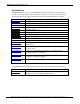
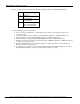
HMC7000 Series I/O Module Guide Introduction The HMC7000 Series (except for the HMC7030A-L) support I/O expansion modules. These modules provide digital and/or analog I/O (inputs and outputs) for an electrical control system. All of the I/O Modules are CE and UL Certified. The following I/O Modules are available: I/O Module Part No.
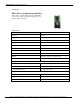
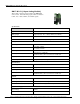
HMC7000 Series I/O Module Guide I/O Modules HMC7-MI-01 (16 Digital Input Module) This module is a digital input module for the HMC7000 Series models. It has sixteen bidirectional inputs, two of which are high-speed inputs. Specifications: Power 3.9 VDC from HMC7000 base Approvals CE, UL Digital Inputs 16 bidirectional inputs (2 high-speed ) Rated input current Up to 5mA (per contact) Input impedance 4.
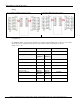
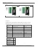
HMC7000 Series I/O Module Guide Wiring: For connecting to NPN-type transistor inputs: Connecting to PNP-type transistor inputs: Configuration: Use MAPware-7000 to assign input (X and XW) and configuration (M and MW) memory addresses to the module. These addresses are created according to the slot location of the module, where nn refers to the slot number (ex.
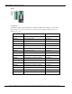
HMC7000 Series I/O Module Guide Reference the table below when configuring each HSC Configuration Register (MWnn00 and MWnn06): Bits Function 15-4 Not used 3 0 : Falling Edge 1 : Rising Edge Module Operating Mode : 000 : Normal Operation 010 : Up Counter HSC 2, 1, 0 To implement High Speed Counter Operation: 1. 2. 3. 4. 5. 6. 7. Connect a device to X0 (Channel 1) or X5 (Channel 2) that will provide the high speed pulses to the expansion module.
HMC7000 Series I/O Module Guide HMC7-MI-02 (4 Input Analog Module) This module is an analog input module for the HMC7000 Series models. It has four analog inputs, which can measure 0-10V, -10 to +10V, 0-20mA, and 4-20mA signals. Specifications: Power 3.9 VDC from HMC7000 base Approvals CE, UL Analog Inputs 4 Inputs (0-10V, -10 to +10V, 0-20mA, and 4-20mA) Resolution 12 bit Connection method Removable terminals (3.
HMC7000 Series I/O Module Guide Wiring: For connecting to analog voltage inputs: Connecting to analog current inputs: Configuration: Use MAPware-7000 to assign input (XW) and configuration (MW) memory addresses to the module. These addresses are created according to the slot location of the module, where nn refers to the slot number (ex.
HMC7000 Series I/O Module Guide HMC7-MI-03 (8 Voltage Input Analog Module) This module is an analog input module for the HMC7000 Series models. It has eight analog inputs, which can measure 0-10V, and -10 to +10Vsignals. Specifications: Power 3.9 VDC from HMC7000 base Approvals CE, UL Analog Inputs 8 Inputs (0-10V, -10 to +10V) Resolution 12 bit Connection method Removable terminals (3.81 mm pitch) Voltage Mode Input range -10V to +10V, 0 - 10V Value of LSB: For 0-10V: 2.44mV For +/-10V: 4.
HMC7000 Series I/O Module Guide Wiring: Configuration: Use MAPware-7000 to assign input (XW) and configuration (MW) memory addresses to the module. These addresses are created according to the slot location of the module, where nn refers to the slot number (ex.
HMC7000 Series I/O Module Guide Reference the table below when configuring each Input Configuration Register (MWnn00-MWnn07): Input Channel Signal Type Voltage (0 - 10V) Value 1 Voltage (-10 to +10V) 2 Phone: 425/745-3229 • Fax: 425/745-3429 • Email: maple@maplesystems.com • www.maplesystems.com . 1010-1043 Page 9 of 85 Rev.
HMC7000 Series I/O Module Guide HMC7-MI-04 (8 Current Input Analog Module) This module is an analog input module for the HMC7000 Series models. It has eight analog inputs, which can measure 0-20mA, and 4-20mA signals. Specifications: Power 3.9 VDC from HMC7000 base Approvals CE, UL Analog Inputs 8 Inputs (0-20mA, 4-20mA) Resolution 12 bit Connection method Removable terminals (3.81 mm pitch) Voltage Mode Input range 0-20mA, 4-20mA Value of LSB: 3.
HMC7000 Series I/O Module Guide Wiring: Configuration: Use MAPware-7000 to assign input (XW) and configuration (MW) memory addresses to the module. These addresses are created according to the slot location of the module, where nn refers to the slot number (ex.
HMC7000 Series I/O Module Guide Reference the table below when configuring each Input Configuration Register (MWnn00-MWnn07): Input Channel Signal Type Current (0 - 20mA) Value 3 Current (4 – 20mA) 0 Phone: 425/745-3229 • Fax: 425/745-3429 • Email: maple@maplesystems.com • www.maplesystems.com . 1010-1043 Page 12 of 85 Rev.
HMC7000 Series I/O Module Guide HMC7-MO-01 (12 Relay Output Module) This module is a digital output module for the HMC7000 Series models. It has twelve relay outputs. Specifications: Power 3.9 VDC from HMC7000 base Approvals CE, UL Digital Outputs 12 relay outputs Turn ON Time 10 msec Turn OFF Time 5 msec Output capacity 2A per contact up to 230VAC 2A per contact up to 30VDC Connection method Removable terminals (3.
HMC7000 Series I/O Module Guide Wiring: Configuration: Use MAPware-7000 to assign output (Y and YW), and configuration (MW) memory addresses to the module. These addresses are created according to the slot location of the module, where nn refers to the slot number (ex. 01…05): Register Description Access Ynn000Ynn011 Output Bits Read/Write YWnn00 MWnn00 Output Word Data Relay Output Read/Write Read/Write Phone: 425/745-3229 • Fax: 425/745-3429 • Email: maple@maplesystems.com • www.maplesystems.
HMC7000 Series I/O Module Guide HMC7-MO-02 (16 Sinking Output Module) This module is a digital output module for the HMC7000 Series models. It has 16 sinking (NPN) outputs. Specifications: Power 3.9 VDC from HMC7000 base Approvals CE, UL Digital Outputs 16 sinking (NPN) outputs Turn ON Time 10 msec Turn OFF Time 10 msec Output Capacity 500mA per output maximum Rated load 500mA @ 24VDC Total output capacity 4A @ 24VDC Connection method Removable terminals (3.
HMC7000 Series I/O Module Guide Wiring: Configuration: Use MAPware-7000 to assign output (Y and YW) addresses to the module. These addresses are created according to the slot location of the module, where nn refers to the slot number (ex. 01…05): Register Description Access Ynn000Ynn015 Output Bits Read/Write YWnn00 Output Word Data Read/Write Phone: 425/745-3229 • Fax: 425/745-3429 • Email: maple@maplesystems.com • www.maplesystems.com . 1010-1043 Page 16 of 85 Rev.
HMC7000 Series I/O Module Guide HMC7-MO-03 (16 Sourcing Output Module) This module is a digital output module for the HMC7000 Series models. It has 16 sourcing (PNP) outputs. Specifications: Power 3.9 VDC from HMC7000 base Approvals CE, UL Digital Outputs 16 sourcing (PNP) outputs Turn ON Time 10 msec Turn OFF Time 10 msec Output Capacity 500mA per output maximum Rated load 500mA @ 24VDC Total output capacity 4A @ 24VDC Connection method Removable terminals (3.
HMC7000 Series I/O Module Guide Wiring: Configuration: Use MAPware-7000 to assign output (Y and YW) addresses to the module. These addresses are created according to the slot location of the module, where nn refers to the slot number (ex. 01…05): Register Description Access Ynn000Ynn015 Output Bits Read/Write YWnn00 Output Word Data Read/Write Phone: 425/745-3229 • Fax: 425/745-3429 • Email: maple@maplesystems.com • www.maplesystems.com . 1010-1043 Page 18 of 85 Rev.
HMC7000 Series I/O Module Guide HMC7-MIO-01 (8 Bidirectional Input, 8 Sinking Output Digital Module) This module is a digital input/output module for the HMC7000 Series models. It has eight bidirectional inputs and eight sinking digital outputs. Two of the inputs can be configured as high speed counters (HSC) using the MW registers (see below). When used as HSCs, input X0 (channel 1) and X5 (channel 2) are used to record the incoming pulses. Specifications: Power 3.
HMC7000 Series I/O Module Guide Input Power Supply Input Voltage 24VDC Input Current 4A maximum Wiring: For connecting to bidirectional inputs: Connecting to NPN-type transistor outputs: Phone: 425/745-3229 • Fax: 425/745-3429 • Email: maple@maplesystems.com • www.maplesystems.com . 1010-1043 Page 20 of 85 Rev.
HMC7000 Series I/O Module Guide Configuration: Use MAPware-7000 to assign input (X and XW), output (Y and YW), and configuration (M and MW) memory addresses to the module. These addresses are created according to the slot location of the module, where nn refers to the slot number (ex.
HMC7000 Series I/O Module Guide To implement High Speed Counter Operation: 1. 2. 3. 4. 5. 6. 7. Connect a device to X0 (Channel 1) or X5 (Channel 2) that will provide the high speed pulses to the expansion module. Configure the HSC using the configuration register MWnn00 (Channel 1) or MWnn06 (Channel 2). Write the HSC preset count value in MWnn03 (Channel 1) or MWnn09 (Channel 2). Enable the HSC by setting the HSC Enable Bit Mnn080 (Channel 1) or Mnn176 (Channel 2).
HMC7000 Series I/O Module Guide HMC7-MIO-02 (8 Bidirectional Input, 8 Sourcing Output Digital Module) This module is a digital input/output module for the HMC7000 Series models. It has eight bidirectional inputs and eight sourcing digital outputs. Two inputs can be configured as high speed counters (HSC) using the MW registers (see below). When used as HSCs, input X0 (channel 1) and X5 (channel 2) are used to record the incoming pulses. Specifications: Power 3.
HMC7000 Series I/O Module Guide Input Power Supply Input Voltage 24VDC Input Current 4A maximum Wiring: For connecting to bidirectional inputs: Connecting to PNP-type sourcing outputs: Phone: 425/745-3229 • Fax: 425/745-3429 • Email: maple@maplesystems.com • www.maplesystems.com . 1010-1043 Page 24 of 85 Rev.
HMC7000 Series I/O Module Guide Configuration: Use MAPware-7000 to assign input (X and XW), output (Y and YW), and configuration (M and MW) memory addresses to the module. These addresses are created according to the slot location of the module, where nn refers to the slot number (ex.
HMC7000 Series I/O Module Guide To implement High Speed Counter Operation: 1. 2. 3. 4. 5. 6. 7. Connect a device to X0 (Channel 1) or X5 (Channel 2) that will provide the high speed pulses to the expansion module. Configure the HSC using the configuration register MWnn00 (Channel 1) or MWnn06 (Channel 2). Write the HSC preset count value in MWnn03 (Channel 1) or MWnn09 (Channel 2). Enable the HSC by setting the HSC Enable Bit Mnn080 (Channel 1) or Mnn176 (Channel 2).
HMC7000 Series I/O Module Guide HMC7-MIO-03 (2 Input 2 Output Analog Module) This module is an analog input/output module for the HMC7000 Series models. It has two analog inputs, which can be used to measure 0-10V, -10 to +10V, 0-20mA, and 420mA signals. It also has two analog outputs to provide 010V, 0-20mA, and 4-20mA signals. Specifications: Power 3.
HMC7000 Series I/O Module Guide Current Mode Output Range 4mA-20mA Value of LSB 3.9 μA Output Load Maximum 500 Ohm Accuracy At 25°C: 0.2% of full scale Overall Accuracy (-25°C to 55°C) 0.8% of full scale Current Mode Output Range 0mA-20mA Value of LSB 4.8 µA Output Load Maximum 500 Ohm Accuracy At 25°C: 0.
HMC7000 Series I/O Module Guide Wiring: For connecting to analog voltage inputs: For connecting to analog current inputs: Connecting to analog voltage outputs: Connecting to analog current outputs: Configuration: Use MAPware-7000 to assign input (XW), output (YW), and configuration (MW) memory addresses to the module.
HMC7000 Series I/O Module Guide Reference the table below when configuring each Input/Output Configuration Register (MWnn00MWnn03) Input Channel Signal Type mA (4-20mA) Voltage (0-10V) Voltage (-10 to +10V) mA (0-20mA) Output Channel Signal Type mA (4-20mA) Voltage (0-10V) Reserved mA (0-20mA) Value 0 1 2 3 Value 0 1 2 3 Phone: 425/745-3229 • Fax: 425/745-3429 • Email: maple@maplesystems.com • www.maplesystems.com . 1010-1043 Page 30 of 85 Rev.
HMC7000 Series I/O Module Guide HMC7-MIO-04 (8 Bidirectional Input, 8 Sinking Output Digital Module) This module is a digital input/output module for the HMC7000 Series models. It has eight bidirectional inputs and eight sinking digital outputs. Four of the inputs can be configured as high speed counters (HSC) using the MW registers (see below). When used as HSCs, input X0 (channel 1), X5 (channel 2), X2 (channel 3), and X7 (channel 4) are used to record the incoming pulses. Specifications: Power 3.
HMC7000 Series I/O Module Guide High Speed Channels No. of Outputs 2 channels (Y2 and Y4) General Operating Temperature 0 to 55°C Operating Humidity 10% to 90% (non condensing) Mechanical Dimension (LxWxH) 3.11x1.18x1.42 inches [79x30x36mm] Input Power Supply Input Voltage 24VDC Input Current 4A maximum Wiring: Connecting to High-Speed inputs: Connecting to Normal inputs: Phone: 425/745-3229 • Fax: 425/745-3429 • Email: maple@maplesystems.com • www.maplesystems.com .
HMC7000 Series I/O Module Guide Connecting to Sinking PWM Outputs: Configuration: Use MAPware-7000 to assign input (X and XW), output (Y and YW), and configuration (M and MW) memory addresses to the module. These addresses are created according to the slot location of the module, where nn refers to the slot number (ex. 01…05): Function Register Access X0-X7 Inputs Xnn000-007 (XWnn00) Rd Only Y0-Y7 Outputs Ynn000-007 (YWnn00) Rd/Write High Speed Counter Option HSC Input HSC Ch. 1 HSC Ch.
HMC7000 Series I/O Module Guide Quadrature Inputs Pair 1 Pair 2 Counter Inputs X0, X5 X2, X7 Rd Only Counter Reset Input X1 X3 Rd Only Output Flag Y1 Y7 Rd/Write PWM1 PWM2 Y2 Y4 PWM Outputs Output Rd Only Reference the table below when configuring each HSC Configuration Register: Input Mode Output Mode Register Value Normal Input N/A 0 High Speed, Single Phase, Up Counter Output ON when preset is reached 2 258 Quadrature 1X Output ON when counter is enabled, OFF when preset i
HMC7000 Series I/O Module Guide Reference the tables below when configuring the PWM outputs: Normal PWM Function Register Output Y2 Y4 Physical Output Configuration Register MWnn24 MWnn30 Value = 1 for this mode Frequency Setting Register1 MWnn25 MWnn25 Range = 1 to 10000 MWnn26 MWnn26 MWnn27 MWnn31 MWnn28 MWnn32 Output Enable Flag MWnn36_0 MWnn36_1 Enabled when ON ON Duty Setting Error Flag MWnn29_2 MWnn29_7 ON = error (resets automatically) Frequency Setting Error Flag MWnn29_
HMC7000 Series I/O Module Guide Pulse/Direction Function Register Description Output, PWM Pulse Y2 Physical Output Output, PWM Direction Y4 Configuration Register MWnn24 Value = 7 for this mode Frequency Setting Register Output Enable Flag MWnn25 MWnn26 MWnn36_0 Range = -10000 to -1; 1 to 10000 Enabled when ON Frequency Setting Error Flag MWnn29_3 ON = error (resets automatically) Fixed Pulse Mode Function Register Description Output, PWM Pulse Y2 Physical Output Configuration Registe
HMC7000 Series I/O Module Guide To implement PWM Operation: 1. 2. 3. 4. 5. 6. Configure the PWM output using the configuration register for that channel and mode. Set the parameters values for the selected mode. Monitor the error flags for the parameters. Enable the output by setting the Enable Output that channel. HSC increments the current value register for that channel until the preset value is reached. Enable the HSC Reset Bit by setting for that channel.
HMC7000 Series I/O Module Guide HMC7-MIO-05 (8 Bidirectional Input, 8 Sourcing Output Digital Module) This module is a digital input/output module for the HMC7000 Series models. It has eight bidirectional inputs and eight sinking digital outputs. Four of the inputs can be configured as high speed counters (HSC) using the MW registers (see below). When used as HSCs, input X0 (channel 1), X5 (channel 2), X2 (channel 3), and X7 (channel 4) are used to record the incoming pulses. Specifications: Power 3.
HMC7000 Series I/O Module Guide High Speed Channels No. of Outputs 2 channels (Y2 and Y4) General Operating Temperature 0 to 55°C Operating Humidity 10% to 90% (non condensing) Mechanical Dimension (LxWxH) 3.11x1.18x1.42 inches [79x30x36mm] Input Power Supply Input Voltage 24VDC Input Current 4A maximum Wiring: Connecting to High-Speed inputs: Connecting to Normal inputs: Phone: 425/745-3229 • Fax: 425/745-3429 • Email: maple@maplesystems.com • www.maplesystems.com .
HMC7000 Series I/O Module Guide Connecting to Sinking PWM Outputs: Phone: 425/745-3229 • Fax: 425/745-3429 • Email: maple@maplesystems.com • www.maplesystems.com . 1010-1043 Page 40 of 85 Rev.
HMC7000 Series I/O Module Guide Configuration: Use MAPware-7000 to assign input (X and XW), output (Y and YW), and configuration (M and MW) memory addresses to the module. These addresses are created according to the slot location of the module, where nn refers to the slot number (ex. 01…05): Function Register Access X0-X7 Inputs Xnn000-007 (XWnn00) Rd Only Y0-Y7 Outputs Ynn000-007 (YWnn00) Rd/Write High Speed Counter Option HSC Ch. 1 HSC Ch. 2 HSC Ch. 3 HSC Ch.
HMC7000 Series I/O Module Guide Reference the table below when configuring each HSC Configuration Register: Input Mode Output Mode Register Value Normal Input N/A 0 High Speed, Single Phase, Up Counter Output ON when preset is reached 2 258 Quadrature 1X Output ON when counter is enabled, OFF when preset is reached Output ON when preset is reached 259 Quadrature 2X Output ON when counter is enabled, OFF when preset is reached Output ON when preset is reached 323 Quadrature 4X Output ON when
HMC7000 Series I/O Module Guide Reference the tables below when configuring the PWM outputs: Normal PWM Function Register Output Y2 Y4 Physical Output Configuration Register MWnn24 MWnn30 Value = 1 for this mode Frequency Setting Register1 MWnn25 MWnn25 Range = 1 to 10000 MWnn26 MWnn26 MWnn27 MWnn31 MWnn28 MWnn32 Output Enable Flag MWnn36_0 MWnn36_1 Enabled when ON ON Duty Setting Error Flag MWnn29_2 MWnn29_7 ON = error (resets automatically) Frequency Setting Error Flag MWnn29_
HMC7000 Series I/O Module Guide Pulse/Direction Function Register Description Output, PWM Pulse Y2 Physical Output Output, PWM Direction Y4 Configuration Register MWnn24 Value = 7 for this mode Frequency Setting Register MWnn25 MWnn26 Range = -10000 to -1; 1 to 10000 Output Enable Flag MWnn36_0 Enabled when ON Frequency Setting Error Flag MWnn29_3 ON = error (resets automatically) Function Register Description Output, PWM Pulse Y2 Physical Output Configuration Register MWnn24 Val
HMC7000 Series I/O Module Guide To implement PWM Operation: 7. 8. 9. 10. 11. Configure the PWM output using the configuration register for that channel and mode. Set the parameters values for the selected mode. Monitor the error flags for the parameters. Enable the output by setting the Enable Output that channel. HSC increments the current value register for that channel until the preset value is reached. Enable the HSC Reset Bit by setting for that channel.
HMC7000 Series I/O Module Guide HMC7-MIO-06 (8 Bidirectional Input, 6 Relay, 2 Sinking Output Digital Module) This module is a digital input/output module for the HMC7000 Series models. It has eight bidirectional inputs and six relay outputs (3 per common), plus two sinking digital outputs. Four of the inputs can be configured as high speed counters (HSC) using the MW registers (see below).
HMC7000 Series I/O Module Guide High Speed Channels No. of Outputs 2 channels (Y2 and Y4) General Operating Temperature 0 to 55°C Operating Humidity 10% to 90% (non condensing) Mechanical Dimension (LxWxH) 3.11x1.18x1.42 inches [79x30x36mm] Input Power Supply Input Voltage 24VDC Input Current 4A maximum Wiring: For connecting to high-speed inputs: For connecting to normal inputs: Phone: 425/745-3229 • Fax: 425/745-3429 • Email: maple@maplesystems.com • www.maplesystems.com .
HMC7000 Series I/O Module Guide For connecting to PWM outputs: For connecting to relay outputs: Phone: 425/745-3229 • Fax: 425/745-3429 • Email: maple@maplesystems.com • www.maplesystems.com . 1010-1043 Page 48 of 85 Rev.
HMC7000 Series I/O Module Guide Configuration: Use MAPware-7000 to assign input (X and XW), output (Y and YW), and configuration (M and MW) memory addresses to the module. These addresses are created according to the slot location of the module, where nn refers to the slot number (ex. 01…05): Function Register Access X0-X7 Inputs Xnn000-007 (XWnn00) Rd Only Y0-Y7 Outputs Ynn000-007 (YWnn00) Rd/Write High Speed Counter Option HSC Ch. 1 HSC Ch. 2 HSC Ch. 3 HSC Ch.
HMC7000 Series I/O Module Guide Reference the table below when configuring each HSC Configuration Register: Input Mode Output Mode Register Value Normal Input N/A 0 High Speed, Single Phase, Up Counter Output ON when preset is reached 2 258 Quadrature 1X Output ON when counter is enabled, OFF when preset is reached Output ON when preset is reached 259 Quadrature 2X Output ON when counter is enabled, OFF when preset is reached Output ON when preset is reached 323 Quadrature 4X Output ON when
HMC7000 Series I/O Module Guide Reference the tables below when configuring the PWM outputs: Normal PWM Function Register Output Y2 Y4 Physical Output Configuration Register MWnn24 MWnn30 Value = 1 for this mode Frequency Setting Register1 MWnn25 MWnn25 Range = 1 to 10000 MWnn26 MWnn26 MWnn27 MWnn31 MWnn28 MWnn32 Output Enable Flag MWnn36_0 MWnn36_1 Enabled when ON ON Duty Setting Error Flag MWnn29_2 MWnn29_7 ON = error (resets automatically) Frequency Setting Error Flag MWnn29_
HMC7000 Series I/O Module Guide Pulse/Direction Function Register Description Output, PWM Pulse Y2 Physical Output Output, PWM Direction Y4 Configuration Register MWnn24 Value = 7 for this mode Frequency Setting Register MWnn25 Range = -10000 to -1; MWnn26 1 to 10000 Output Enable Flag MWnn36_0 Enabled when ON Frequency Setting Error Flag MWnn29_3 ON = error (resets automatically) Function Register Description Output, PWM Pulse Y2 Physical Output Configuration Register MWnn24 V
HMC7000 Series I/O Module Guide To implement PWM Operation: 13. 14. 15. 16. 17. Configure the PWM output using the configuration register for that channel and mode. Set the parameters values for the selected mode. Monitor the error flags for the parameters. Enable the output by setting the Enable Output that channel. HSC increments the current value register for that channel until the preset value is reached. Enable the HSC Reset Bit by setting for that channel.
HMC7000 Series I/O Module Guide HMC7-MIO-07 (8 Bidirectional Input, 6 Relay, 2 Sourcing Output Digital Module) This module is a digital input/output module for the HMC7000 Series models. It has eight bidirectional inputs and six relay outputs (3 per common), plus two sinking digital outputs. Four of the inputs can be configured as high speed counters (HSC) using the MW registers (see below).
HMC7000 Series I/O Module Guide Specifications: Power 3.9 VDC from HMC7000 base Approvals CE, UL Digital Inputs 8 bidirectional inputs Rated input voltage 24 VDC Rated input current Up to 5mA Input impedance 4.9K ohms Minimum ON voltage 15 VDC Maximum OFF voltage 5 VDC Turn ON Time 10 msec Turn OFF Time 10 msec Isolation Optically isolated from internal circuit Connection method Removable terminals (3.81 mm pitch) High Speed Channels No.
HMC7000 Series I/O Module Guide Wiring: For connecting to high-speed inputs: For connecting to normal inputs: For connecting to PWM outputs: For connecting to relay outputs: Phone: 425/745-3229 • Fax: 425/745-3429 • Email: maple@maplesystems.com • www.maplesystems.com . 1010-1043 Page 56 of 85 Rev.
HMC7000 Series I/O Module Guide Configuration: Use MAPware-7000 to assign input (X and XW), output (Y and YW), and configuration (M and MW) memory addresses to the module. These addresses are created according to the slot location of the module, where nn refers to the slot number (ex. 01…05): Function Register Access X0-X7 Inputs Xnn000-007 (XWnn00) Rd Only Y0-Y7 Outputs Ynn000-007 (YWnn00) Rd/Write High Speed Counter Option HSC Ch. 1 HSC Ch. 2 HSC Ch. 3 HSC Ch.
HMC7000 Series I/O Module Guide Reference the table below when configuring each HSC Configuration Register: Input Mode Output Mode Register Value Normal Input N/A 0 High Speed, Single Phase, Up Counter Output ON when preset is reached 2 258 Quadrature 1X Output ON when counter is enabled, OFF when preset is reached Output ON when preset is reached 259 Quadrature 2X Output ON when counter is enabled, OFF when preset is reached Output ON when preset is reached 323 Quadrature 4X Output ON when
HMC7000 Series I/O Module Guide Reference the tables below when configuring the PWM outputs: Normal PWM Function Register Output Y2 Y4 Physical Output Configuration Register MWnn24 MWnn30 Value = 1 for this mode Frequency Setting Register1 MWnn25 MWnn25 Range = 1 to 10000 MWnn26 MWnn26 MWnn27 MWnn31 MWnn28 MWnn32 Output Enable Flag MWnn36_0 MWnn36_1 Enabled when ON ON Duty Setting Error Flag MWnn29_2 MWnn29_7 ON = error (resets automatically) Frequency Setting Error Flag MWnn29_
HMC7000 Series I/O Module Guide Pulse/Direction Function Register Description Output, PWM Pulse Y2 Physical Output Output, PWM Direction Y4 Configuration Register MWnn24 Value = 7 for this mode Frequency Setting Register MWnn25 Range = -10000 to -1; MWnn26 1 to 10000 Output Enable Flag MWnn36_0 Enabled when ON Frequency Setting Error Flag MWnn29_3 ON = error (resets automatically) Function Register Description Output, PWM Pulse Y2 Physical Output Configuration Register MWnn24 V
HMC7000 Series I/O Module Guide To implement PWM Operation: 19. 20. 21. 22. 23. Configure the PWM output using the configuration register for that channel and mode. Set the parameters values for the selected mode. Monitor the error flags for the parameters. Enable the output by setting the Enable Output that channel. HSC increments the current value register for that channel until the preset value is reached. Enable the HSC Reset Bit by setting for that channel.
HMC7000 Series I/O Module Guide HMC7-MIO-08 (4 Input Analog / 2 Analog Output Module) This module is an analog input/output module for the HMC7000 Series models. It has four universal analog inputs, which can measure 0 to 50mV, 0 to 100 mV; 0 to 10V, 0 to 5v, -10 to +10V; 0 to-20mA, 4-20mA; PT100 RTD (alpha1, alpha2), PT1000 RTD; Type J, K Thermocouple (15-minute warm-up recommended) It also has two analog outputs, configurable as 0 to 5V, 0 to 10V; 0 to 20mA, 4 to 20mA; Specifications: Power 3.
HMC7000 Series I/O Module Guide Input Power Supply Input Voltage 24VDC Input Current 80mA (max) Wiring: For connecting to analog voltage inputs: Connecting to analog current inputs: Phone: 425/745-3229 • Fax: 425/745-3429 • Email: maple@maplesystems.com • www.maplesystems.com . 1010-1043 Page 63 of 85 Rev.
HMC7000 Series I/O Module Guide For connecting to RTD inputs: For connecting to voltage outputs For connecting to mV/thermocouple inputs: For connecting to current outputs Phone: 425/745-3229 • Fax: 425/745-3429 • Email: maple@maplesystems.com • www.maplesystems.com . 1010-1043 Page 64 of 85 Rev.
HMC7000 Series I/O Module Guide Configuration: Use MAPware-7000 to assign input (XW) and configuration (MW) memory addresses to the module. These addresses are created according to the slot location of the module, where nn refers to the slot number (ex.
HMC7000 Series I/O Module Guide Reference the table below when configuring each Input Configuration Register (MWnn00-MWnn03): Input Channel Signal Type Voltage, 0 to 10V Value 1 Voltage, 0 to 5V 6 Voltage, -10 to +10V 18 Voltage, 0 to 50mV 5 Voltage, 0 to 100mV 4 Current, 4 to 20mA 2 Current, 0 to 20mA 3 RTD, PT100, alpha11 7 RTD, PT100, alpha21 8 RTD, PT1000 9 Thermocouple, Type J2 14 Thermocouple, Type K2 15 Notes: 1. alpha1= 0.00385 Ω/Ω/°C, alpha2=0.003926 Ω/Ω/°C 2.
HMC7000 Series I/O Module Guide HMC7030A-L (12 digital inputs and 8 digital outputs built-in) This unit has built-in I/O. It has 12 directional inputs, 6 relay outputs and 2 sinking NPN outputs. Specifications: Power 24VDC ± 15%, 3W Approvals CE, UL Digital Inputs 12 bidirectional inputs Rated input voltage 24 VDC Rated input current Up to 5mA Input impedance 4.
HMC7000 Series I/O Module Guide General Operating Temperature Operating Humidity 0 to 50°C 10% to 90% (non condensing) Mechanical Dimension (LxWxH) 5.04x4.02x1.77 inches [128x102x45mm] Panel Cutout 4.69x3.55 inches [119x93mm] Wiring: For connecting to bidirectional inputs: Connecting to outputs: Phone: 425/745-3229 • Fax: 425/745-3429 • Email: maple@maplesystems.com • www.maplesystems.com . 1010-1043 Page 68 of 85 Rev.
HMC7000 Series I/O Module Guide Configuration: Use MAPware-7000 to assign input (X and XW), output (Y and YW), and configuration (M and MW) memory addresses to the module.
HMC7000 Series I/O Module Guide 6. 7. Enable the HSC Reset Bit by setting M00241 (Channel 1) or M00401 (Channel 2). Or by setting Reset Pin X4 (Channel 1) or Reset Pin X5 (Channel 2). This will cause the HSC current value to reset back to 0 and the output Y0 (Channel 1) or output Y1 (Channel 2) will reset (clear) to 0. To start the process again, simply reset (clear) the HSC Reset Bit and set the HSC Enable Bit.
HMC7000 Series I/O Module Guide Common Terms for I/O Modules This section defines some common terms used to describe various types of input and output modules. The terms explained below are generic descriptions. Be sure to consult the datasheet for the specific requirements when installing and wiring a module. Digital Modules Digital Modules provide physical connections and interpretations of input devices using discrete signals.
HMC7000 Series I/O Module Guide Note: arrow indicates current flow direction In order to have current flow, each I/O terminal on the expansion module must have a return path or a signal ground connection. In most modules, multiple I/O terminals share the signal ground connection. Digital Outputs (PNP or NPN type) The output terminals of a digital I/O module use an optically isolated PNP or NPN transistor to energize the connected load.
HMC7000 Series I/O Module Guide Digital Outputs (Relay type) The output terminals of a relay-type digital module typically control loads that require an AC power source: Use a Relay Output module to connect a DC load that requires more current than the maximum available when using a PNP or NPN output. For AC loads, each relay output contact can handle up to 230VAC with a 2A load per contact. For DC loads, each relay output contact can handle a 2A load per contact for up to 30VDC.
HMC7000 Series I/O Module Guide In addition, many of the I/O modules have a two-pin connector that is used to connect a voltage source (usually +24VDC). This voltage source drives the output terminals of the I/O modules. Installing I/O Modules The expansion modules for the HMC7000 snap onto the back of the HMC7000 thru expansion slots. The HMC7030A-M and HMI7035A-M units support up to three modules. The HMC7057A-M unit supports up to five modules.
HMC7000 Series I/O Module Guide 5. Select from the list box, the particular I/O expansion module installed in Slot 1 of the HMC7000. When the checkbox to ‘Add tags for XW, YW, and MW’ is checked, MAPware-7000 automatically assigns tags to the Tag Database for the I/O module. The tags configured are based upon the module and the slot location. Click OK. 6. In this example, Slot1 is identified with an IO module, along with a description and memory address allocation.
HMC7000 Series I/O Module Guide Configuration of the HMC7000 Series High Speed Counters Maple Systems’ HMC products have built-in High-Speed counters that link directly to specific inputs and outputs. Specific registers and bits are predefined for setup and control of these counters. No logic is required to run the counters, other than logic that may be used to configure and control the counters.
HMC7000 Series I/O Module Guide Configuration Register Bit 15-4 Description Reserved (leave set to 0) Edge Trigger: 3 0 = Falling 1 = Rising Counter Mode: 000 =High Speed Counter Off 2,1,0 010 = High Speed Up Counter Other settings are reserved. Note: You can write to the configuration register value using the Power-Up logic block or in a Power-Up Task. Specific High Speed Counter Registers The registers and I/O associated with the High-Speed Counter depend on the hardware.
HMC7000 Series I/O Module Guide These tags are assigned automatically when a project is created: For products with Modular I/O (Requires the HMC7-MIO-01 or HMC7-MIO-02 module )1 Function Counter 1 Counter 2 Trigger Bit X n000 Xn005 Done Bit Yn001 Yn006 Enable Bit Mn080 Mn176 Reset Bit (Internal, Physical) Mn081, Xn001 Mn177, Xn006 Configuration Register MWn00 MWn06 Current Count Register (LSW, MSW) MWn01, MWn02 MWn07, MWn08 Preset Register (LSW, MSW) MWn03, MWn04 MWn09, MWn10 Not
HMC7000 Series I/O Module Guide For example, a module installed in Slot 3 has the following assignments: Function Counter 1 Counter 2 Trigger Bit X03000 X03005 Enable Bit M03080 M03176 Done Bit Y03001 Y03006 Reset Bit (Internal, Physical) M03081, X03001 M03177, X03006 Configuration Register MW0300 MW0306 Current Count Register (LSW, MSW) MW0301, MW0302 Preset Register (LSW, MSW) MW0303, MW0304 MW0307, MW0308 MW0309, MW0310 These tags are assigned automatically when the module is added
HMC7000 Series I/O Module Guide Some Sample Ladder Logic These two rungs configure the High Speed Counters in a unit that has built-in I/O. The HMC ladder logic requires an input condition on each rung. The input bits are the Normally Closed contacts of an otherwise unused bit. The Move Word instructions write a value of 2 (00000010b) to the Configuration Register of each High Speed Counter. This sets Bit 1 and leaves all other bits reset.
Maple Systems Inc. th 808 134 Street SW, Suite 120 Everett, WA 98204-7333 Phone: (425) 745-3229 Email: maple@maplesystems.com Web: www.maplesystems.com © 2011 Maple Systems Inc. All rights reserved.