
Specifications
5.5.2 Preparing for Installation
The following procedure for installing RA9x disk drives is applicable to SA600,
SA650, SA800, and SA850 storage arrays.
The RA9x add-on kit includes the following items:
• RA9x disk drive
• Hardware mounting kit
• Guide rail plate assembly
• Power cord
• Port identification labels
Use the following procedure to prepare for installing an RA9x disk drive:
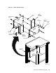
1. To protect the operator control panel (OCP) during installation, remove it by
gently pulling it straight out from the front of the disk drive, as shown in
Figure 5–4. Put the OCP in a safe place while completing the remainder of
the installation.
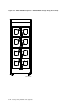
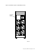
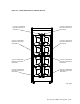
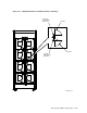
2. Figures 5–5 and 5–6 define the recommended sequence for adding storage
devices to the cabinets. The number assigned to each cabinet location is the
recommended sequence for adding units. Use these figures to determine the
device cabinet position. The first SA7x enclosure is always mounted in the
top left position (as viewed from the front) in an SA650 or SA850 storage
array.
3. Remove the front and rear cabinet panels as described in Sections 4.1.1 and
4.1.2.
4. Take off the front panel bezel filler from the device cabinet position by
removing the four U-clips from the back side of the front door that hold the
bezel filler in place. The bezel filler will come free.
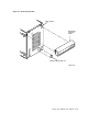
5. Connect the two chassis retaining brackets to the disk drive using the four
short pan-head screws (8-32 x 1/4-inch) and washers as shown in Figure 5–7.
Each hardware package contains four chassis retaining brackets:
• Two for an H9646 storage array cabinet installation
• Two for an H9A00 storage array installation
Figure 5–7 shows the chassis retaining brackets used for this installation.
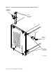
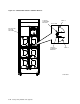
6. Remove the chassis stabilizer bracket shown in Figures 5–8, 5–9, and 5–10
from the cabinet by removing the two serrated hex-head bolts. Set these parts
aside.
5–10 Storage Array Add-Ons and Upgrades