
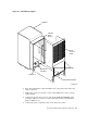
Specifications
15. Disconnect all power cords from the power controller and pull them through
the opening in the power controller.
16. Remove the kepnut that secures the grommet bracket around the power
cable. Remove the grommet bracket. Keep the kepnut and the bracket in
a safe place.
17. Pull the external power cable up through the hole in the base of the cabinet
bustle.
18. Lift the power controller up and out of the cabinet.
19. Remove the L-shaped bracket from the power controller by removing the allen
screw that attaches it to the controller. Keep the bracket and screw in a
safe place.
Use the following procedure to replace the power controller:
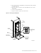
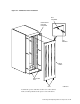
1. Install the L-shaped mounting bracket on the power controller. (Refer to
Figure 4–8.)
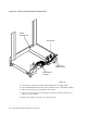
2. Lift the power controller into the cavity at the base of the cabinet.
3. Position the controller so that you can connect the power cords on the left side
of the controller.
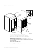
4. Route the external power cord through the hole in the cabinet bustle base.
Install the grommet bracket and secure it with the kepnut.
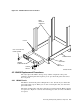
5. Position the power controller so that the mounting screw holes are aligned.
6. Install the four screws to connect the power controller to the frame. (Refer to
Figure 4–6.)
7. Pass the power cords through the opening in the power controller and
connect the storage device power cords to the same receptacles on the
controller. This is necessary to ensure phase balance is maintained. (Refer to
Figure 4–8.)
8. Coil excess power cord towards the front of the cabinet. Secure the cables
with a cable tie, then connect the cable tie to the cable tie mount in the base.
9. Reinstall any enclosures that were removed, secure them with the mounting
screws, and connect the internal SDI cables and the power cords.
10. Connect the power controller power cord to the power source.
11. Set the power controller circuit breaker (CB1) to the on (up) position.
12. Set the Bus/Off/On switch on the power controller to the on (bottom) position.
13. Turn on all storage devices and place them on line.
14. Check out each storage device for proper operation as described in the user
guide or service manual.
15. Lift the rear panel into place and fit the pins into the holes located at the top
of the filler panel.
16. Push the top of the panel into place and turn the fasteners one-quarter turn
clockwise to lock.
4–12 Removing and Replacing Cabinet Components