
Specifications
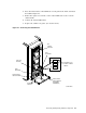
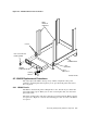
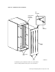

Figure 4–5 Power Controller Power Cord Connections
COM-0119
POWER
CONTROLLER
RECEPTACLE
DISK DRIVE
POWER CORDS
CABLE MOUNT /
TIE WRAP
10. Set the power controller circuit breaker (CB1) to the on (up) position.
11. Set the Bus/Off/On switch on the power controller to the on (bottom) position.
12. Turn on all storage devices and place them on line.
13. Check out each storage device for proper operation as described in the user
guide or service manual.
14. Replace the cabinet rear panel. (See Section 4.1.2.)
4–8 Removing and Replacing Cabinet Components