
Specifications
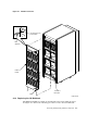
4.1.4 Replacing the Power Controller
Use the following procedure to remove the power controller located in the bottom
of the H9646 cabinet behind the I/O bulkhead:
1. Take all storage devices in the cabinet off line and spin them down.
2. Remove the cabinet rear panel.
3. Set the power on/off switch on all storage devices to the off position.
4. Set the power controller Bus/Off/On switch to the off (center) position.
5. Set the power controller circuit breaker (CB1) to the off (down) position.
6. Unplug the power cord from the power source.
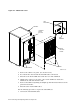
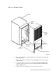
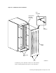
7. Remove the I/O bulkhead without disconnecting the SDI cables.
Unfasten the captive screw in the center of the bulkhead and rotate the
bulkhead out and down from the unit. (Refer to Figure 4–3.)
8. Lift the bulkhead straight up until the bottom slots clear the pins in the I/O
frame.
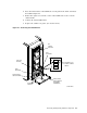
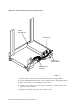
9. The bulkhead support, shown in Figure 4–4, is secured by one wing nut on
each side. Remove these wing nuts and lift the bulkhead support out of the
cabinet. Keep the wing nuts in a safe place.
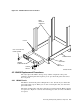
10. Remove the two screws on each side that secure the power controller to the
cabinet frame as shown in Figure 4–6. Keep the screws in a safe place.
11. Slide the power controller forward until you can reach the power cords
connected to the left side, shown in Figure 4–5.
12. Record the power cord connections.
13. Disconnect all power cords from the power controller.
14. Pull the power controller’s external power cord up through the hole in the
base of the cabinet bustle.
15. Lift the power controller up and out of the cabinet.
Refer to Figures 4–4 and 4–6 and use the following procedure to install a power
controller:
1. Lift the power controller into the cavity at the base of the cabinet.
2. Route the external power cord through the hole in the cabinet bustle base.
3. Position the power controller so that the mounting screw holes align with the
frame rail mounting holes.
4. Install the screws to connect the power controller to the frame, as shown in
Figure 4–6.
5. Replace the bulkhead support and install one wing number on each side.
(Refer to Figure 4–4.)
4–6 Removing and Replacing Cabinet Components