
Specifications


3.5.2 H9A00 SDI Cable Connections
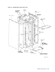
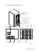
The H9A00 cabinet includes a left and a right vertical I/O bulkhead. To access
these bulkheads, you must first remove the cabinet’s rear panel. (Refer to
Figure 3–9.)
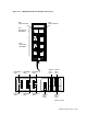
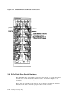
Figures 3–13 and 3–14 show the I/O bulkhead locations for connecting RA9x and
SA7x external SDI cables, respectively, to the SA900 storage array.
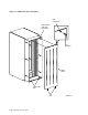
After connecting the external SDI cables, route them through the two slots in the
filler panel. To feed cables through the slots more easily:
1. First remove the cable retainers by removing the two screws that secure each
retainer. (Refer to Figure 3–8.)
2. Push the cables back into the slots.
3. When all cables are positioned in the slots, replace the cable retainers.
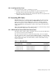
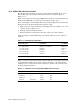
Table 3–2 lists the external SDI cables. For dual porting, two sets of cables are
required.
Table 3–2 H9A00 External SDI Cables
External SDI Cables
Standard
Part Number
Fire Code
Part Number
3.7 m (12 ft) cable BC26V–12 or BC26G–12 BC26J–12
7.6 m (25 ft) cable BC26V–25 BC26J–25
7.6 m (25 ft) cable
1
BC27V-25 None
15.2 m (50 ft) cable BC26V–50 BC26J–50
24.4 m (80 ft) cable BC26V–80 BC26J–80
1
TA8x7 series storage systems only
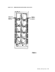
Table 3–3 describes the SA7x enclosure internal SDI cable connections to the Port
A and Port B I/O bulkhead connectors as shown in Figure 3–14. Early model
cabinets used color coded wires. Newer models use a label on the connector that
identifies the RA7x position.
Table 3–3 SA7x Enclosure Internal SDI I/O Bulkhead Connections
RA7x Position I/O Connector Wire Color Label
Right front 1 (top) White RF
Left front 2 Red LF
Right rear 3 Black RR
Left rear 4 (bottom) Yellow LR
3–20 Installing a Storage Array