
Specifications
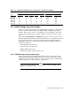
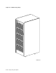
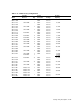
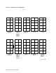
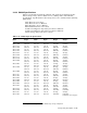
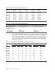
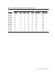


Table 2–18 SA650 and SA850 Electrical Specifications—240/416 Vac 50/60 Hz
Input Current (Amps) Power Dissipation
Model Start-Up PH1 PH2 PH3 Neutral Watts Kilojoules/Hr
SA650–FD
SA650–HD
SA650–JD
7.2
10.5
10.5
0.3
2.2
4.1
1.9
1.9
5.9
4.0
5.9
5.9
4.4
6.6
9.3
941
1507
2398
3388
5425
8633
SA850–FD
SA850–HD
SA850–JD
7.2
10.5
10.5
0.3
2.2
4.1
1.9
1.9
5.9
4.0
5.9
5.9
4.4
6.6
9.3
941
1507
2398
3388
5425
8633
2.14 SA900 Storage Array Description
There are several SA900 storage array configurations composed of combinations
of SA7x enclosures, RA92 disk drives, ESE50 SSDs, and TA857 tape storage
systems. These storage devices are installed in a five-level H9A00 cabinet and
receive power through a power controller. Figure 2–4 shows an SA900 storage
array.
There is no standard SA900 configuration, therefore, SA900 storage arrays
are not shipped with mounting rails, internal SDI cables, or bulkhead connectors
for any add-on storage devices. The hardware required is shipped with the
individual storage device. Instructions for installing the following add-ons are
contained in Chapter 5:
• RA9x disk drives (Section 5.7)
• SA7x enclosures (Section 5.11)
• ESE50 SSDs (Section 5.8)
• TA8x7 tape storage system (Section 5.12)
2.14.1 SA900 Storage Array Configurations
Table 2–19 lists the factory configurations for the SA900 storage arrays. All
configurations comply with DSA requirements and can be used with any SDI
controller protocol and cable. Figures 2–5 and 5–18 show factory configurations
and the storage device add-on sequence, respectively.
Note
There are no SA900 factory configurations that include the ESE50. The
ESE50 is a field add-on only.
Storage Array Descriptions 2–15