
Specifications
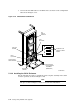
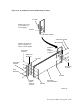

1. Position the guide rail plate on the left or right side of the cabinet frame,
depending on which side the enclosure will be installed.
2. Use three shoulder screws and lock washers to connect the back of the guide
rail plate to the back of the cabinet frame. Fasten the screws into the nut bar
behind the frame.
3. Use four 10-32 x 5/8-inch flat-head screws to connect the mounting bracket
and mounting rail to the front cabinet frame. Fasten the screws into the nut
bar in front of the mounting rail.
4. Use three 10-32 x 7/16-inch shoulder screws and lock washers to connect the
front of the mounting bracket to the front of the cabinet frame. Fasten the
screws into the nut bar behind the frame.
5. Install the SA7x enclosures as explained in (Section 5.10).
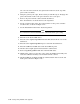
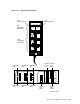
5.13.5 Installing SDI Cables and Power Cords
Use the following procedure to install the SDI cables and power cords as shown
in Figures 5–47 and 5–49:
1. Connect the SDI cables to the Port A and Port B connectors on the rear of the
SA7x enclosure.
2. Lift up and push back the cable trough on the right.
3. Route the SA7x internal SDI cables through the cable trough on the right.
4. Connect SA7x internal SDI cables to the SA7x I/O panel as shown on the
configuration label in Figure 5–47.
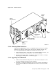
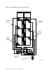
5. Make sure that the SA7x front panel drive power switches and the rear panel
Master On/Off power switch are off.
6. Make sure that the line voltage selection is in the correct position (120 Vac or
240 Vac).
7. Connect the power cord to the SA7x enclosure.
8. Verify that the enclosure power cord is connected to either J7 or J8 on the
power controller as shown in Figure 5–49.
5–74 Storage Array Add-Ons and Upgrades