
Specifications
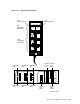


Use a hex wrench to turn the two quarter-turn fasteners at the top of the
panel counter-clockwise.
4. Grasp the panel by the edges, tilt it toward you and lift it up to disengage the
pins at the bottom. Remove the panel and store it in a safe place.
5. Remove all power from the cabinet and the disk drives.
Place the disk drive circuit breakers to the off position.
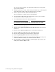
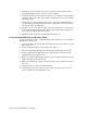
6. Set the circuit breaker in the off (center) position on the power controller
circuit breaker, as shown in Figure 5–45.
7. Set the Bus/Off/On switch in the off (down) position.
Note
Record internal and external SDI cable connections before proceeding.
8. Disconnect all external SDI cables.
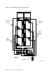
9. Disconnect the top level position internal SDI cables from the rear of the
disk drives.
10. Disconnect the top level position power cords from the disk drives.
11. Disconnect all internal SDI cables from the bulkhead panel.
12. Lift the cable troughs upward and toward the cabinet front.
13. Remove top level position disk drive internal SDI cables.
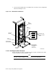
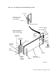
14. Unfasten the captive screw in the center of the I/O bulkhead assembly and
rotate the bulkhead assembly out and down from the cabinet.
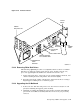
15. Lift the bulkhead assembly straight up until its bottom slots clear the I/O
frame pins as shown in Figure 5–46.
5–70 Storage Array Add-Ons and Upgrades