
Specifications
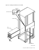
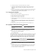
6. Connect the SCSI terminator into the upper connector on the TZ8x7 tape
subsystem.
7. Connect the the 7.6 meter (25 foot) SDI/STI external interface cable to either
the Port A (left) or the Port B (right) connector on the adapter-interface.
8. Route the external SDI cable behind the right bulkhead and out the bottom of
the cabinet. Connect to the controller connector on the bulkhead.
5.12.4 Completing the Installation
Complete the following installation procedure:
1. On the rear of the TZ8x7 tape subsystem, set the SCSI node ID on the DIP
switches.
2. Restore power to the cabinet as explained in Section 3.9.
3. Turn on all disk drives, tape drives, and SCSI/SDI adapter-interfaces.
4. Spin up all drives and place them on line.
5. Verify that all devices are functioning properly by completing the checkout
procedures described in the appropriate device user guide or service manual.
6. Replace the rear cabinet panel.
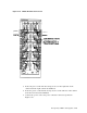
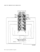
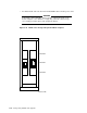
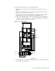
5.13 Upgrading an SA600/SA800 Storage Array to an SA650/SA850
Storage Array
This section contains instructions for upgrading the SA600 or SA800 storage
array to an authorized SA650 or SA850 storage array configuration.
SA600/SA800 storage arrays have internal SDI cables and power cords factory
installed for eight RA90 or RA92 disk drives, respectively. To upgrade to an
SA650 or SA850 storage array configuration, you must remove the factory
installed SDI cabling and the RA9x drives installed in the top level positions.
Figure 5–44 shows the tested and authorized SA650 and SA850 storage array
configurations.
5–68 Storage Array Add-Ons and Upgrades