
Specifications
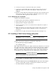

Use the following procedure to connect the TA8x7 cables:
1. Make sure the circuit breaker for the TZ8x7 tape subsystem is in the off
position.
2. Make sure voltage settings on the rear of the TZ8x7 subsystem match the
cabinet. These switches are not settable.
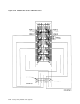
3. Connect the power cords to the TZ8x7 tape subsystem and the SCSI/SDI
adapter-interface to the power controller, as shown Figure 5–43.
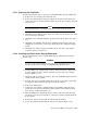
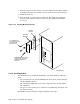
4. Connect the SCSI/SDI adapter cable to the adapter-interface SCSI/SDI bus
connector, as shown in Figure 5–43. Only one SCSI/SDI cable connector is
compatible with the SCSI/SDI bus connector.
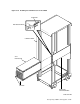
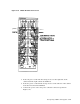
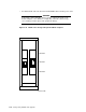
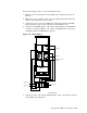
Figure 5–43 TA8x7 Cabling
J4 J5 J6 J1
J3
J7 J8 J9 J2
J0
O1 (PHASE 1)
POSITION 1
POSITION 2
POSITION 3
O2 (PHASE 2)
O3 (PHASE 3)
CXO-3554A-MC
INTERNAL SCSI-SDI
CABLE
5. Connect the other end of the SCSI/SDI adapter cable to the bottom connector
on the TZ8x7 tape subsystem.
Storage Array Add-Ons and Upgrades 5–67