
Specifications

5.12.1 Preparing for Installation
Use the following procedure to prepare for installing TA8x7 storage subsystems:
1. Remove the rear cabinet panel and front door.
2. Remove the grill from the front door. From the back side of the front door,
remove the four screws that hold the grill to the front door opening. The grill
will come free.
Note
The following steps are performed from the rear side of the front door.
3. Install the trim weldment on the same side as the door latch and secure with
two screws (8-32 x 1/4-inch).
4. Install the bezel weldment with the opening nearest to the inner edge of the
door.
5. Install the bezel stiffner onto the bezel weldment under the lip of the door,
aligning the screws holes over the four studs and secure with four kepnuts
(8-32).
6. Install the two guide rail plate assemblies in the tape drive and adapter
locations. (Refer to Section 5.6.)
5.12.2 Installing the TA8x7 Series Storage Subsystem
Use the following procedure to install TA8x7 storage subsystem in an SA900
storage array:
WARNING
To prevent injury when lifting an object weighing approximately 24.95 kgs
(55 lbs), use at least two people or a Digital-approved lifting device.
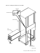
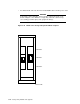
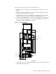
1. Lift the TZ8x7 tape subsystem into position at the front of the cabinet, place
it on the right side of the cabinet, and slide it part way into the cabinet.
(Refer to Figure 5–11.)
2. Using the same procedure as in Step 1, place the SCSI/SDI adapter-interface
on the left side of the cabinet.
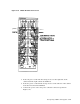
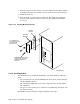
3. Seat the side grooves of both components securely on the cabinet guide rails
(see Figure 5–42) and slide them part way into the cabinet.
4. Remove the lifting device.
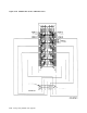
5. Connect the two chassis retaining brackets to the TZ8x7 using the short
pan-head screws (10-32 x 1/4-inch) and inserting the screws into the front
pair of holes, as shown in Figure 5–37.
6. Slide the TZ8x7 tape subsystem into the cabinet and secure with the long
pan-head screws (10-32 x 3/4-inch) to connect the chassis retaining brackets
to the cabinet.
7. Remove the top two screws from the left front of the adapter.
8. Secure the adapter bracket with the two screws. Refer to Figure 5–42.
Storage Array Add-Ons and Upgrades 5–65