
Specifications


Use the following procedure to prepare for SA7x enclosure installation:
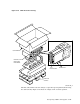
1. To protect the OCP during installation, remove it from the enclosure front
panel by pulling it straight out. Put the OCP in a safe place while completing
the remainder of the installation.
2. Remove the front and rear cabinet panels. (See Sections 4.1.1 and 4.1.2.)
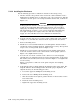
3. Remove the bezel filler in the front panel position.
On an SA650 or SA850 storage array, remove the six U-clips from the back
side of the front panel and remove the bezel filler.
On an SA550 storage array, remove the nuts from the back of the bezel filler
and pull out the bezel filler.
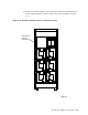
4. If the cabinet has a stabilizer foot installed, extend it. (Refer to Figure 5–1.)
5. Position both the steel inserts shown in Figure 5–28 on either the left or right
side of the enclosure.
6. Position the guide rail inserts for a SA550, SA650, and SA850 storage arrays
left side installation.
Note
If the SA550, SA650, or SA850 storage array is to be installed on the
right side, proceed to step 7.
a. Loosen the two rear cover captive screws (or two screws) and remove the
rear cover.
b. Remove the two upper right chassis retainer screws and remove the
retainer bracket.
c. Slide the upper right insert out the rear of the enclosure.
d. Slide the insert into the upper left side of the enclosure.
e. Install the retainer bracket and insert and tighten the two chassis
retainer screws.
f. Install the rear cover and insert and tighten the two rear cover captive
screws (or two screws).
7. Position the guide rail inserts for a SA550, SA650, or SA850 storage array
right-side installation.
a. Loosen the two power supply captive screws and remove the power supply.
b. Remove the two lower left chassis retainer screws and remove the retainer
bracket.
c. Slide the lower left insert out the rear of the enclosure.
d. Slide the insert into the lower right side of the enclosure.
e. Install the retainer bracket and insert and tighten the two chassis
retainer screws.
f. Install the power supply and tighten the two captive screws.
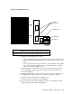
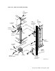
8. Connect the top and bottom chassis retaining brackets to the cabinet’s front
vertical upright, as shown in Figure 5–29.
5–44 Storage Array Add-Ons and Upgrades