
Specifications
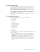
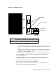
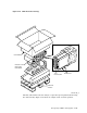
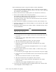
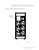

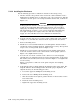

Figure 5–25 ESE50 Rear Panel
PORT
PORT
A
B
FOR CONTINUED PROTECTION AGAINST RISK OF FIRE,
REPLACE ONLY WITH SAME TYPE AND RATING OF FUSES.
DISCONNECT POWER BEFORE CHANGING FUSE.
COUPER LE COURANT AVANT DE REMPLACER LE FUSIBLE.
WARNING:
CAUTION:
ATTENTION:
1
0
CAUTION
115 VAC
FUSE COVER
AC RECEPTACLE
AC POWER SWITCH
SDI CABLE
CONNECTIONS
2. Install the internal SDI cables as follows:
– Connect cables from drives and enclosures on the left side of the cabinet
to the left vertical I/O bulkhead and secure with two 6-32 x 3/8-inch sems
screws.
– Connect cables from drives and enclosures on the right side of the cabinet
to the right vertical I/O bulkhead and secure with two 6-32 x 3/8-inch
sems screws. (Refer to Figure 5–20.)
3. Connect SDI cables connectors to the Port A and Port B connections on the
rear of the ESE50. Connect the other end of the cable connectors to the
vertical I/O bulkhead.
4. Connect the ESE50 Port A cable to the top port of a group of eight; connect
the ESE50 Port B cable to the next-to-the-top port of a group of eight.
5. Connect the power cords as shown in Figure 5–21.
Connect the power cord to the rear of the ESE50.
6. Route the power cords from the SSD and enclosure on the right side of the
cabinet down the right vertical I/O bulkhead.
Storage Array Add-Ons and Upgrades 5–41