
Specifications
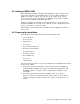
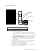
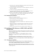
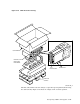
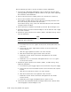
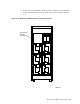

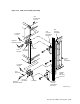
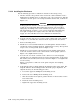

Figure 5–24 ESE50 OCP
ESE50
TESTBAFAULTRUNREADY PROTECT
WRITE
Four−Character Alphanumeric Display
Unit Number
Status
LED
Indicator
RUN
Switch
FAULT
Switch
WRITE
Switch
PORT A
Switch
PORT B
Switch
TEST
Switch
PROTECT
ESE50_OCP
5.9.1 Installing the ESE50 SSD
Use the following procedure to install the ESE50 SSD in the SA900 storage array:
1. Lift the SSD into position at the front of the cabinet with the aid of a Digital-
approved lifting device or with two people. Turn the SSD so its side grooves
are facing toward the cabinet guide rails. (Refer to Figure 5–11.)
2. Seat the side grooves of the SSD securely on the cabinet guide rails and slide
the SSD all the way back.
3. Remove the lifting device.
4. Using the two 10-32 x 3/4-inch pan-head screws that come with the SSD,
connect the two chassis retaining brackets (mounted on the side of the SSD)
to the cabinet.
5. Replace the OCP. The OCP should be installed at the top of the drive. If a
bezel connector cap is in the way, remove it before replacing the OCP. Move
the cap to the bottom connector.
5.9.2 Installing SDI Cables and Power Cords
All internal SDI cables and power cords are factory installed for storage devices
installed at the factory. You must install and route internal SDI cables and power
cords for any storage device and install the mounting hardware.
The H9A00 cabinet includes a left and a right vertical I/O bulkhead. (Refer to
Figure 5–20.) Storage devices are connected by SDI cables to one of the five sets
of eight connectors on each bulkhead. A total of ten devices can be connected
to the I/O bulkheads. The ESE50s use two SDI cables; the SA7x enclosure uses
two special one-to-four cables. Each cable terminates with four connectors that
connect to the bulkhead. The SA900 storage array can accommodate up to 10
SA7x enclosures, RA9x disk drives, ESE50s (a maximum of four ESE50s) or a
combination of these for a maximum of 80 ports.
To install and connect SDI cables and power cords, use the following procedure:
1. Make sure that the Line Voltage Selector switch is in the proper position
and that the ESE50 AC Power switch, as shown in Figure 5–25, is off. (See
Section 3.7 for information about setting the Line Voltage Selector switch.)
5–40 Storage Array Add-Ons and Upgrades