
Specifications

b. Remove the bezel filler.
WARNING
Use care in supporting the guide rail plate. It is heavy and awkward to
position within the cabinet. If possible, use two persons to support and
position the guide rail plate. The guide rail plate may cause injury if
dropped during installation.
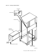
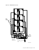
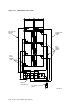
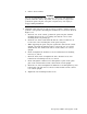
6. Install the guide rail plate in add-on sequence position 3. Add-on sequence
position 3 corresponds to mounting hole numbers 65, 71 and 78 as shown in
Figure 5–17.
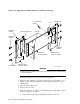
a. From the rear of the cabinet, position the guide rail plate with the
mounting bracket to the rear, making sure that the arrow on the
mounting bracket is pointing up.
b. Insert the two front round stand-offs into the cabinet so that hole 71
becomes the center mounting hole in the guide rail plate.
c. While supporting the guide rail plate against the cabinet front vertical
upright, extend the mounting bracket to engage the two rear round
stand-offs into hole numbers 64 and 79 on the cabinet rear vertical
upright.
d. Insert and tighten the shoulder screws and lockwashers in mounting
holes 65, 71, and 78.
e. From the front, insert and tighten the three shoulder screws and
lockwashers in mounting holes 65, 71, and 78.
f. Insert and tighten a flathead screw through the top hole in the guide
plate to the U-nut mounted on the cabinet front vertical upright.
g. From the rear, insert and tighten two flathead screws through the top and
bottom guide rail plate holes to the two U-nuts mounted on the cabinet
rear vertical upright.
h. Tighten the four mounting bracket screws.
Storage Array Add-Ons and Upgrades 5–27