
Specifications
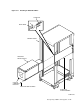
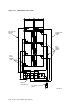
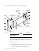
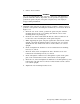

Figure 5–16 Guide Rail Assembly Installation for SA900 Storage Array
MOUNTING BRACKET
FLAT HEAD
SCREWS
NUT BAR
LOCKWASHER
SHOULDER
SCREWS
GUIDE RAIL
PLATE ASSEMBLY
CABINET FRONT
VERTICAL UPRIGHT
CABINET REAR
VERTICAL UPRIGHT
U-NUT
#10-32 MACHINE
SCREW
SHOULDER
SCREWS
LOCKWASHER
MR-0305-92DG
WARNING
Cabinet vertical upright edges may be sharp and can slice or abrade skin
or cable insulation.
1. Turn the cabinet power off as described in Section 5.6.1
2. This procedure installs an enclosure in add-on sequence position 3. (See
Figure 5–18 to select the optimum add-on sequence position for your
installation.)
3. Open the front cabinet door.
4. Remove the rear panel.
5. From the cabinet door, remove the bezel filler that corresponds to add-on
sequence position 3, as follows:
a. Remove the four U-clips securing the bezel filler to the door.
5–26 Storage Array Add-Ons and Upgrades