
Specifications

5.6 Guide Rail Plate Assembly Installation
5.6.1 Preparing the SA900 Cabinet
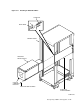
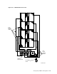
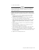
Each enclosure is mounted in the cabinet with one guide rail plate assembly as
shown in Figure 5–16. The guide rail plate is attached to the cabinet’s internal
vertical uprights, and it supports the enclosure from one side. Grooves machined
into the side of the enclosure mate with flanges along the sides of the chassis
rail, allowing the enclosure to slide onto the guide rail plate from the front of the
cabinet.
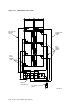
On one end of the guide rail plate is an adjustable mounting bracket. The
mounting bracket has four screws that when loosened, allow the guide rail plate
to be placed into the cabinet and then extended to make a secure fit.
WARNING
While working in the cabinet interior, ac power must be removed from
cabinet components. Failure to do may result in personnel injury as a
result of electric shock.
Prior to performing any of the SA900 procedures, remove ac power from cabinet
components. If the cabinet is installed and operating, spin down all disk drives
and halt tape drives in the cabinet. Switch the circuit breaker on the front of the
cabinet power controller to the (off) position.
5.6.2 Guide Rail Plate Installation
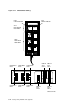
Two round standoffs on each end of the guide rail plate are used to locate the
guide rail plate along the cabinet vertical uprights. The round standoffs are
inserted into the front and rear cabinet vertical upright mounting holes to
position the guide rail plate while it is fastened to the cabinet. Guide rail plate
installation procedures for both left and right enclosure mounting positions are
presented in Sections 5.6.3 and 5.6.4.
If an ESD bolt is mounted to the vertical upright in your selected installation
position, remove the ESD bolt until your installation is complete, then fasten it to
an open space on the cabinet vertical upright.
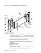
5.6.3 Left Position Guide Rail Plate Installation
Note
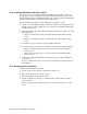
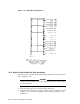
The following instructions are for installing an SA7x enclosure. Other
enclosures use different position numbers as shown in Figure 5–18.
Install the guide rail plate in the left position within the cabinet as follows (see
Figure 5–16):
Storage Array Add-Ons and Upgrades 5–25